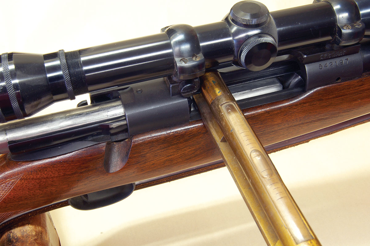
Gil uses a long machinery level to lay across the action rails. Smaller levels are available from gunsmith suppliers.
Our first subject is one that comes up frequently – reticle squaring. What is really meant by that is the alignment of the reticle with the vertical axis of the rifle. This all starts with shots missed at creatures great and small. Then, someone looks through the scope and sagely observes it is no wonder, the reticle isn’t level! Immediately, the owner turns the scope in the rings, not knowing for certain if a problem has been solved or even existed.
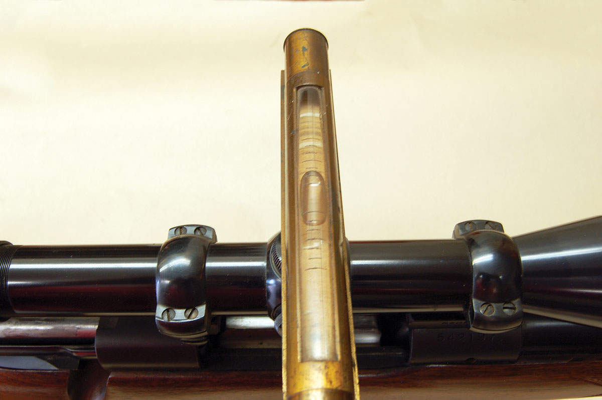
Once the rifle is leveled and locked in place, the level is placed on an elevation turret cap. The ring screws are loosened and the scope is turned until it is level.
Simply put, the eye tends to align the horizontal crossfire parallel to the earth, much like it tends to place the front bead in the center of a peep sight aperture. If the crosswire is not perpendicular to the vertical axis of the rifle when a shot is taken, the crosswire will be unconsciously pulled level, twisting (canting) the rifle to one side. The bullet impact follows the muzzle. Of course, the rifle can be zeroed at one distance, but at any other range, some windage error will occur. However, long-range shooters, who dial-in elevation changes must have the correct alignment or every elevation adjustment will come with a free variable windage change as well.
Aligning the rifle/reticle fairly well by eye is not hard, yet guaranteeing there is no error is easy too. A level is first placed across the bolt raceways. I use an ancient brass machinery level. Small tools are available from gunsmith suppliers. The rifle is clamped solidly in a rifle vise when the device indicates level. Next, the level is placed on the elevation turret cap. It must indicate level here also. If not, turn the scope in the rings until it does. Elevation changes on the range and holdover in the field can now be made with no surprises or excuses.
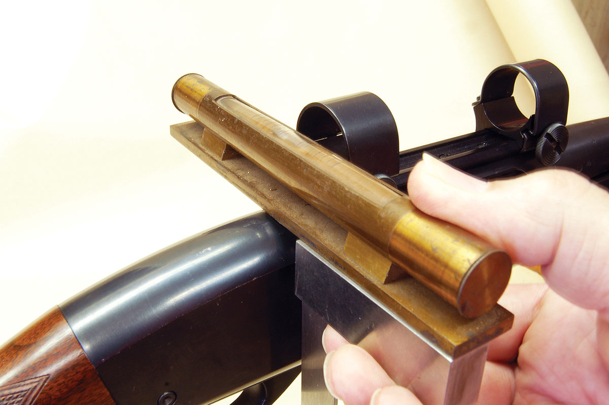
On other than bolt actions, a machinist’s square is held against flat sides to position the level. A Remington Model 760 is shown here.
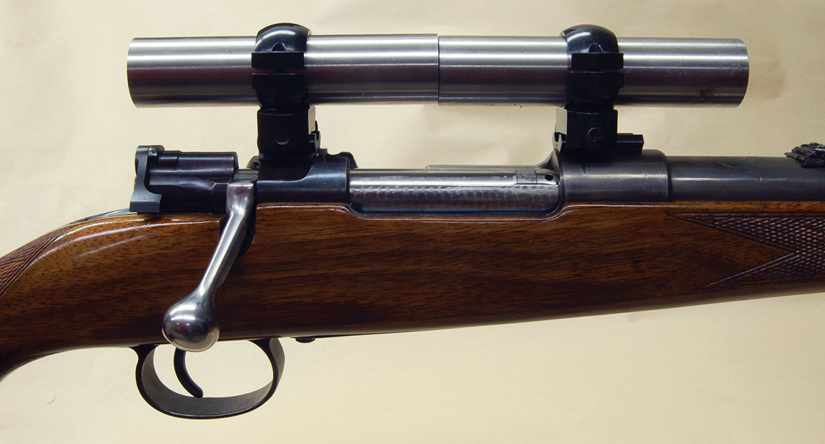
Next is a more important alignment problem. Does the scope tube uniformly contact the inside surface of both mounting rings? In other words, are both rings pointing in the same direction? Making a rifle receiver and scope mounting system in which all the components are in perfect alignment with the breech bolt hole is probably impossible. Trying several ring and base combinations, shimming the assembly and even lapping the rings are commonly required. There is no reason to accept a mount that scratches, dents or bends an expensive scope.
The tools available to indicate ring misalignment are a bit of a puzzle. Most I have seen were made of aluminum or plastic. None would allow measuring misalignment or even indicate exactly the direction of error. This is unacceptable so I will make a proper tool!
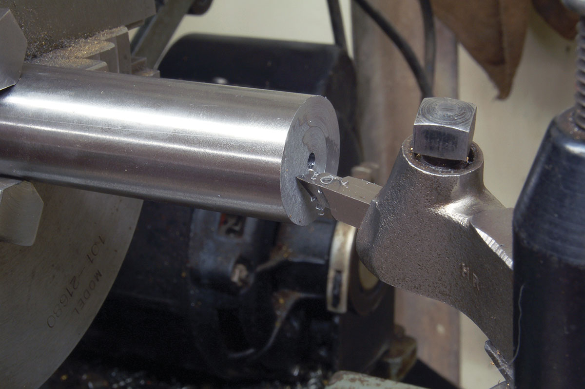
I start by cutting two 4.5-inch long pieces from a 36-inch long stick of 1-inch diameter W-1 (water hardening) drill rod. W-1 is quite hard, tough and wear resistant just as it comes. No heat treatment is needed. The surface finish is finely ground and accurate to .001 inch of state diameter. Such precision is needed and drill rod is the way to get it.
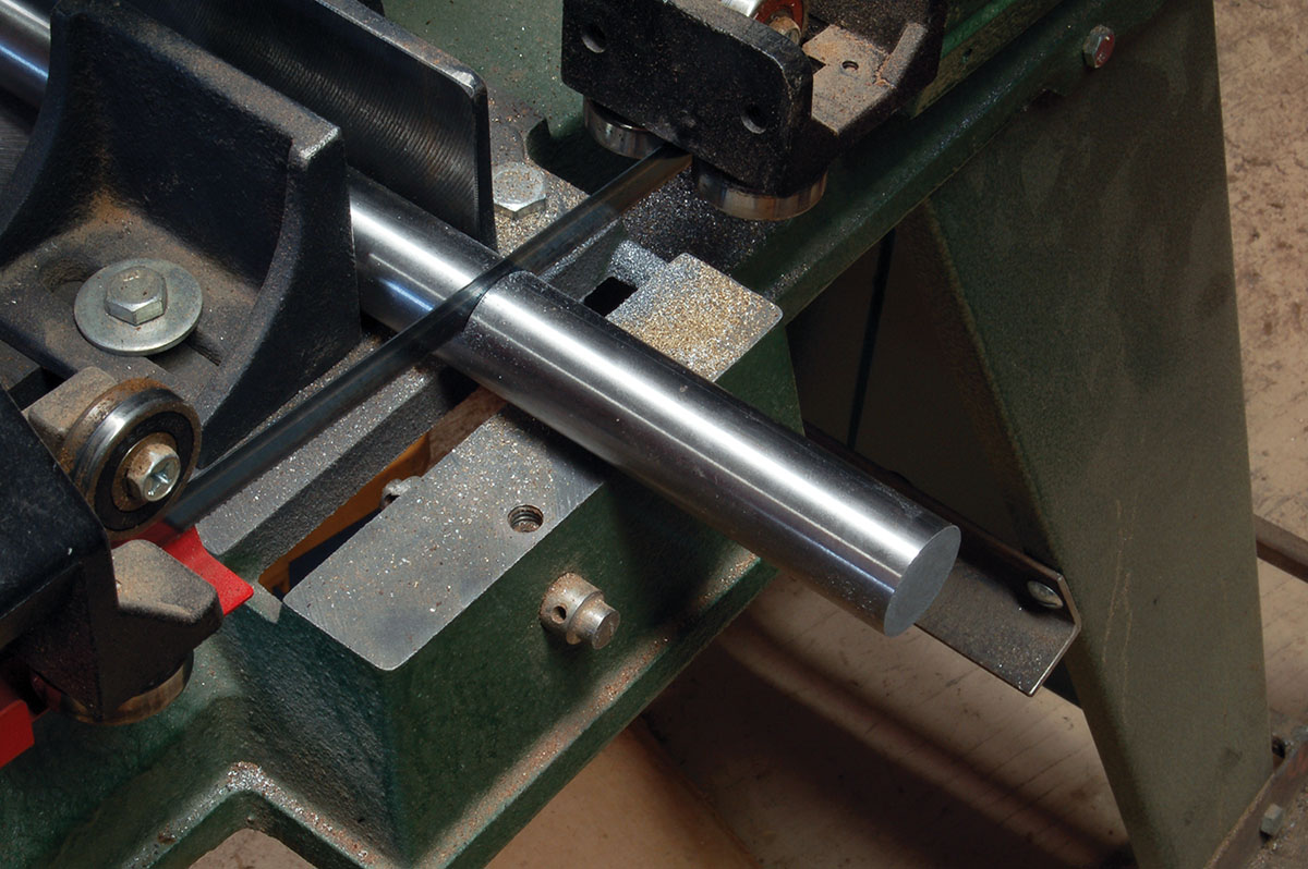
A section of a 1-inch drill rod is being sawed off to make a ring alignment tool.
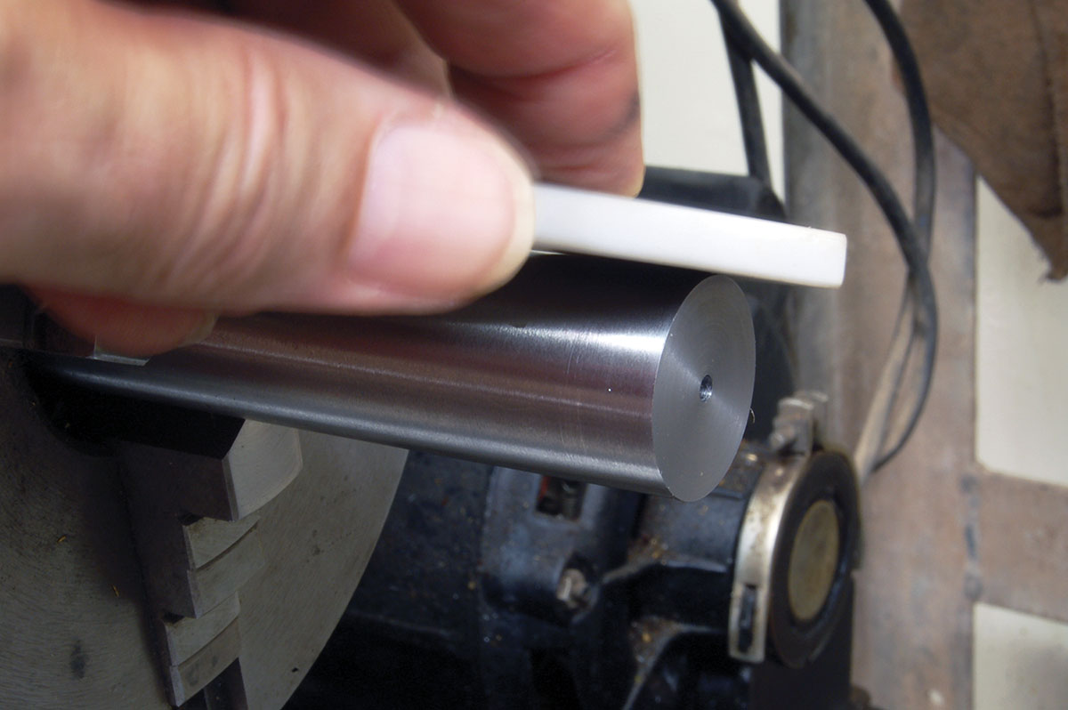
Now, face-off one end of each piece. Of course, this is lathe work. The surface must be perfectly flat. The outside edge here will hold a small burr, which must be removed, preferably with a wide, flat stone. A perfect 90-degreee angle whose edge is so sharp, it will cut is the desired result.
Someone will probably ask about 30mm scope tubes or maybe even the old 26mm. Alignment rods are made the same way. Given America’s plunge toward third-world status, metric dimensioned drill rod is surely available in a bazaar somewhere.
The ends of the alignment rods must be faced-off square with sides, as is being done here.
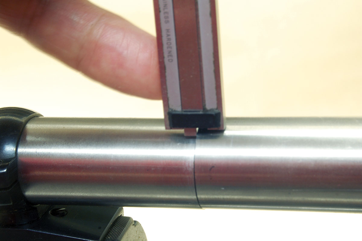
In checking ring alignment – and measuring it – now becomes easy. For example, replacing an existing scope with a new one. Ring screws are removed, the scope is lifted out and replaced with our alignment rods, centered in the opening, flat ends together. Ring tops are put on, screws are pulled tight on one side only. Slide the loose rod to gently touch the other and tighten its screws. Alignment rods must touch, but in no way be forced.
Now, rub a fingertip over the joint where the rods meet. The sharp edge will instantly show any misalignment, which can be measured using the depth feature on a dial caliper. If the rings are twisted a bit, it will show by the rods touching at one point of its circumference and show a small gap directly across from it. This procedure is essentially the same when installing new mounts, except do not use a thread locker because the assembly will probably have to be taken apart a few times.
A tiny burr is left after a facing cut. It must be removed with a flat stone.
With ring misalignment now easy to determine, how much is too much? Answers from scope makers/importers vary from “Less is better, none is best,” to “I have no idea,” to “It depends on the location of the ring on the scope tube.” I have no definitive answer, but I’m told there are a lot of experts dealing with this on the internet so I will leave it to them.
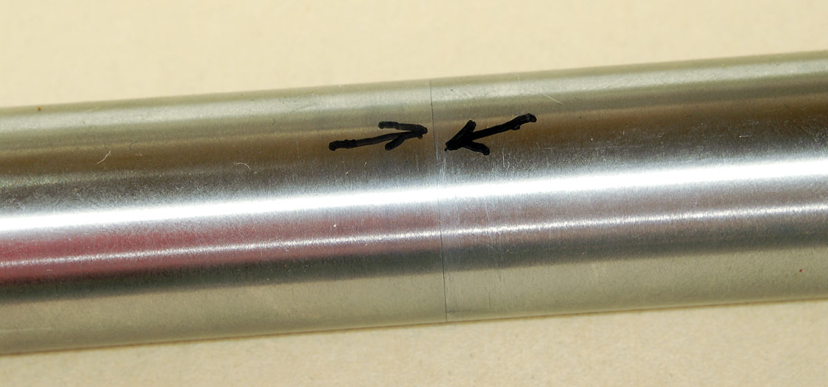
After the burr is removed, the joint of the machined surfaces should be almost invisible.
If much misalignment is detected, the first response today is to grab a scope lapping kit and begin grinding away on the rings. This should be the last option. Rifles have been seen that would not hold the scope under recoil due to excessive lapping. Some had been lapped, but wouldn’t hold the scope tight enough because the inside surface of the rings was no longer flat!
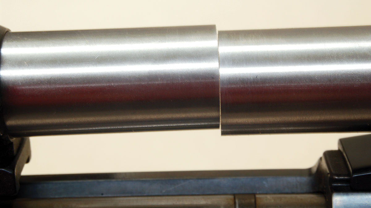
Alignment rods are dropped into rings after a scope was removed. Note the misalignment and also that the rods touch on the near side.
Determining the cause of the inaccuracy is a better place to start. As improbable as this may sound, try turning the rings 180 degrees, one at a time (if the design will allow it), then swapping the rings front to back and finally doing the same to the bases. Check the alignment after each change. If one combination gives better results than the others, the machining of the mount is at fault. Replacement, lapping or ignoring the results are the options.
When moving the parts around gives no change in ring alignment, the scope base holes are not located properly; the two-piece bases are not “pointing in the same direction.” The rifle will almost always be a rebarreled military action or a sporterized military model. For 30 years after World War II, a standard article in gun magazines involved turning “that old military rifle into a valuable sporter that will be cherished for generations to come, etcetera.” All that was required was a few files, some abrasive paper and an electric drill. These were often derisively termed “kitchen table conversions. For what it’s worth, I have never seen one of these that when clamped in a Forster Sight Mounting Fixture had the sight base holes located correctly.
The dial caliper measures the misalignment at .028 inch.
Correcting misaligned holes is time consuming. Bases must be repositioned on the receiver ring and bridge and holes redrilled. If combined with excessive polishing before rebluing, the barrel must be removed, action mounted on a mandrel and the receiver ring and bridge ground uniformly. Custom-fit scope bases are then required. The cost may exceed the value of the rifle.
The foregoing applies to two-piece bases. One-piece, either removable or integral like Picatinny, Ruger and the like are handled differently. For example, if one ring is lower than the other shims must go in the ring under the scope tube.
A good candidate for ring misalignment is a sporterized World War I military rifle fitted with import bases and rings. The misalignment was .037 inch vertically, which was corrected by a shim under the low base.
Correcting any misalignment of scope rings is mostly common sense. The important thing is to have the tools to verify its existence, severity and possible correction before a lot of money is spent on a project or an expensive new scope is ruined.
Next time, I will cover several small items and facts related to scope attaching that have been learned (mostly the hard way) over the years.
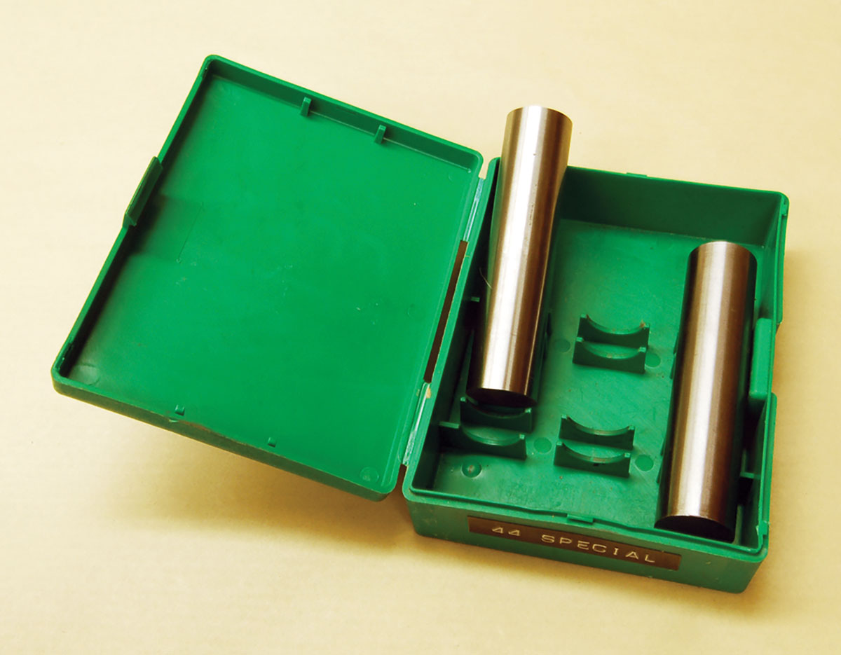
Alignment rods are precision tools. The sharp edge must be preserved, so store the rods properly in a plastic die box.
* * *
Correction: In the last edition of Rifle No. 331 (November – December 2023) in this column, there was a typo in the email address for Leonard Speckin regarding his book. The correct address is lspeckin@4N6.com. We apologize for the error.
