Login


Wolfe Publishing Group
    Menu

    Light Gunsmithing

    Making Simple Tange Sights Part II

    A relief hole is drilled in the elevation slide, followed by a 1⁄16-inch hole to form an aperture.
    A relief hole is drilled in the elevation slide, followed by a 1⁄16-inch hole to form an aperture.
    The rear of the sight staff showing the elevation slide, locking plate and plate attaching screw holes.
    The rear of the sight staff showing the elevation slide, locking plate and plate attaching screw holes.
    In the last issue of Rifle, this column covered simple tang sights used on inexpensive single-shot (non-bolt action) .22 rimfire rifles of the 1880-1950 period. These guns were often referred to as boy’s rifles. Their factory open sights were pretty crude, thus the availability of very cheap (and also crude) tang sights, which were entirely different than the target models of the time.
    A pin in the sight base (arrow) positions the staff vertically. This should have been filled in solid when the base was made, but a spring retainer was originally planned.
    A pin in the sight base (arrow) positions the staff vertically. This should have been filled in solid when the base was made, but a spring retainer was originally planned.

    Few of these sights have survived, but they are easy to make. The one started in the last column took a bit of filing, and I ran out of space before it was finished. It will be completed here along with a second sight that is even simpler, requiring less file work.

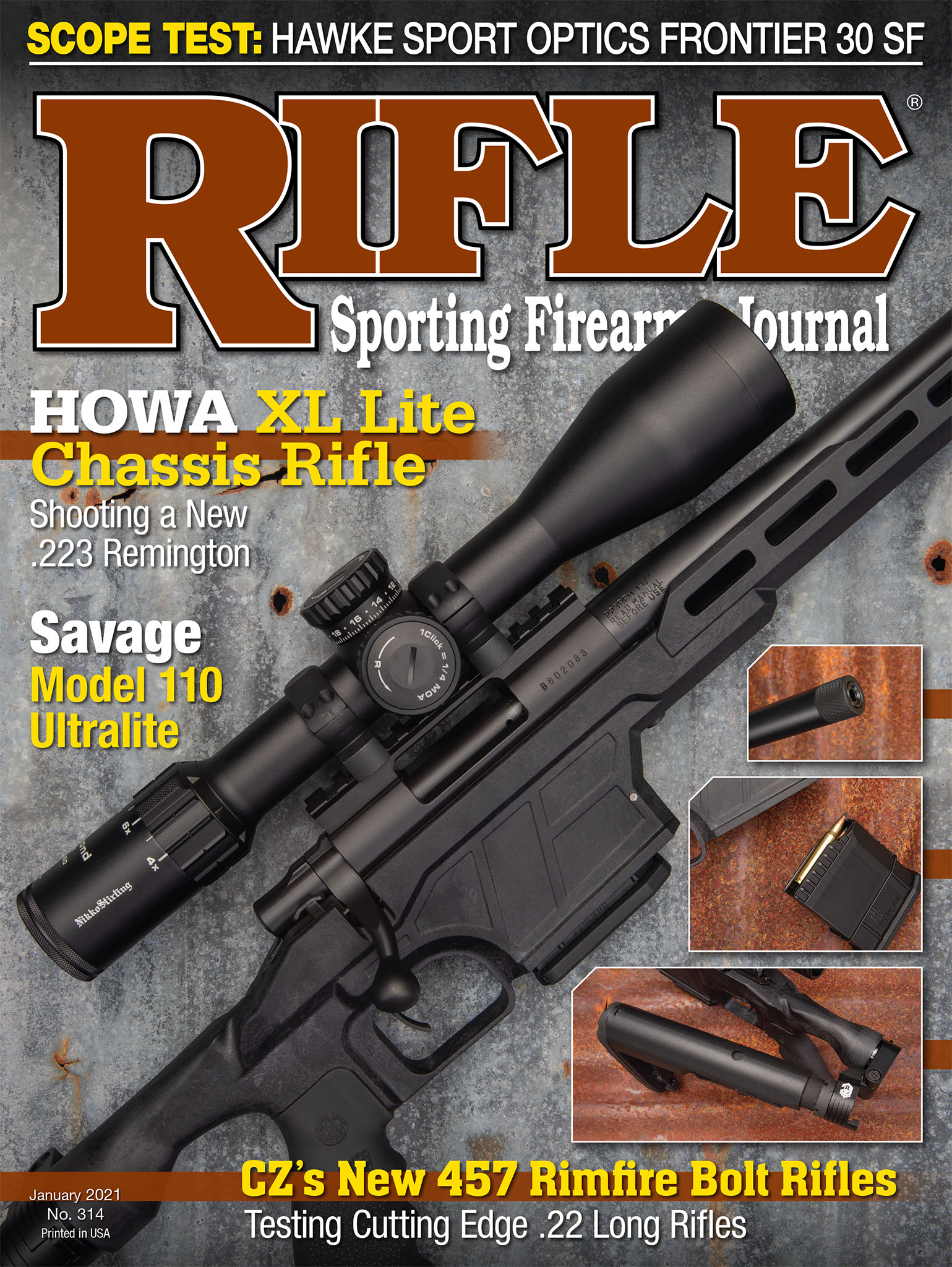
    To complete the sight begun last time, it is necessary to drill the aperture in the elevator slide, install a slide locking plate and make a simple spring to hold the staff in position. Drilling for the aperture must be done on a drill press to prevent breakage of the tiny drill bit. First, however, a relief hole must be drilled on the muzzle side of the slide to eliminate “the fuzzy tunnel-vision” effect of looking through the small diameter aperture. A standard 3⁄16-inch bit is fine. This hole is drilled to within about .050 inch of going completely through. It is followed by the smallest drill in a standard fractional set (1⁄16 inch) to form the aperture.

    The finger-actuated locking knob is being turned to lock the staff in a down position.
    The finger-actuated locking knob is being turned to lock the staff in a down position.
    Next is to make a means of locking the elevation slide to the staff. Use a half-inch square piece of .025-inch thick sheet metal clamped to the rear of the slide by two 5x40 tpi machine screws. This is the standard number 5 screw thread, with screws and taps available from Brownells, if not already on hand. The sheet metal plate overlaps the staff siderails, providing plenty of surface to give a secure friction fit.
    A sight mounted on the Hopkins & Allen project rifle. All sharp edges and square corners have yet to be removed.
    A sight mounted on the Hopkins & Allen project rifle. All sharp edges and square corners have yet to be removed.

    Lastly is a spring holding the staff either vertically or folded down. Springs were made for both sights, but it was decided that fitting and adjusting the small flat springs was just too much bother. Original makers of the cheapest of these sights seldom included springs either, stopping the staff at vertical with a notch or pin in the sight base. Only friction in the hinge joint held it there.

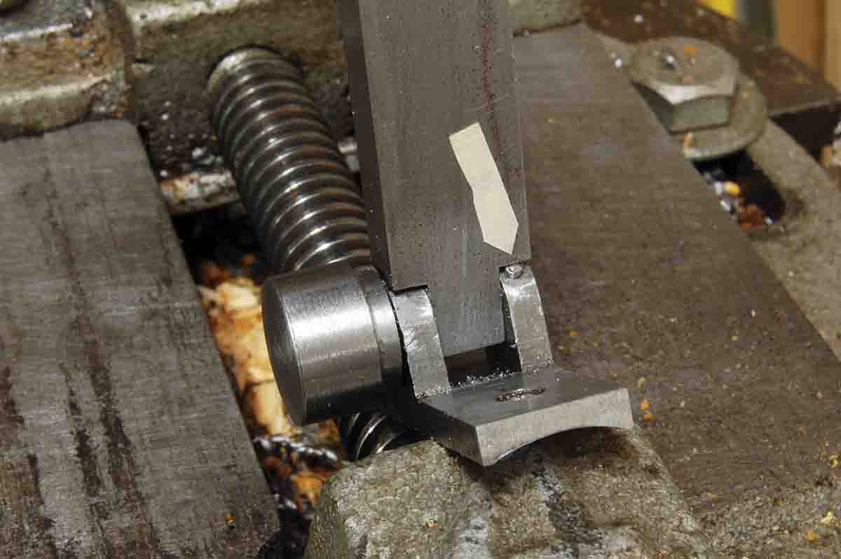
    After years of use, resistance would decrease, causing the sight to move, making it worthless for its intended purpose. This was a bit too crude. Instead of a simple machine screw in the hinge joint, I used a special fastener in both this sight and the one made later. It has a large diameter head that was slotted, but the slot was filed away. It was found at a large hardware store, one of those with a section containing hundreds of little drawers filled with countless varieties of fasteners. Some type of plating that wouldn’t blue also had to be removed.

    The second tang sight begins (left to right) as a length of common square steel tubing, cut to length and one side filed off and a nearly complete base.
    The second tang sight begins (left to right) as a length of common square steel tubing, cut to length and one side filed off and a nearly complete base.
    Now the staff is turned up until it touches the pin in the base (see photo), indicating it is vertical, then the screw is tightened with the fingers, locking it in place. When no longer needed, the screw is loosened, the staff is folded down on the tang and the screw is again tightened. Problem solved, and no spring is needed. A photo shows a complete sight on a falling block Hopkins & Allen .22 rimfire.

    Here the staff has been filed to fit the base, a hole in staff has been drilled and the sides of base shaped so the staff can only move as much as necessary.
    Here the staff has been filed to fit the base, a hole in staff has been drilled and the sides of base shaped so the staff can only move as much as necessary.
    Our second sight is much easier to make. It is also more “basic” looking. The original was seen on a very inexpensive import single-shot rimfire, but it was probably not original to that rifle. Construction was entirely of sheet metal stampings which, of course, isn’t possible in a home shop.
    To determine the height of the base/staff assembly, lay a straightedge over open sights and measure to the tang.
    To determine the height of the base/staff assembly, lay a straightedge over open sights and measure to the tang.

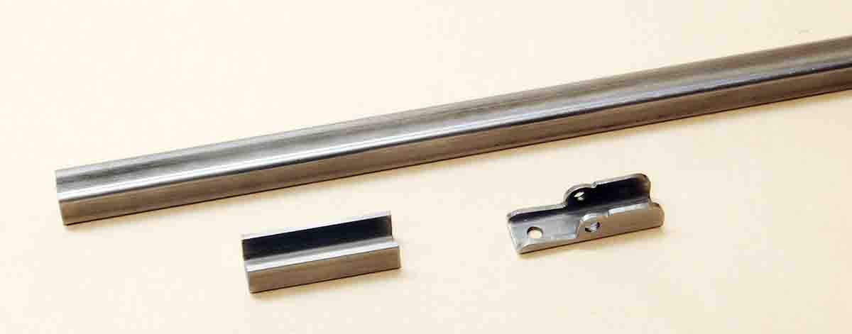
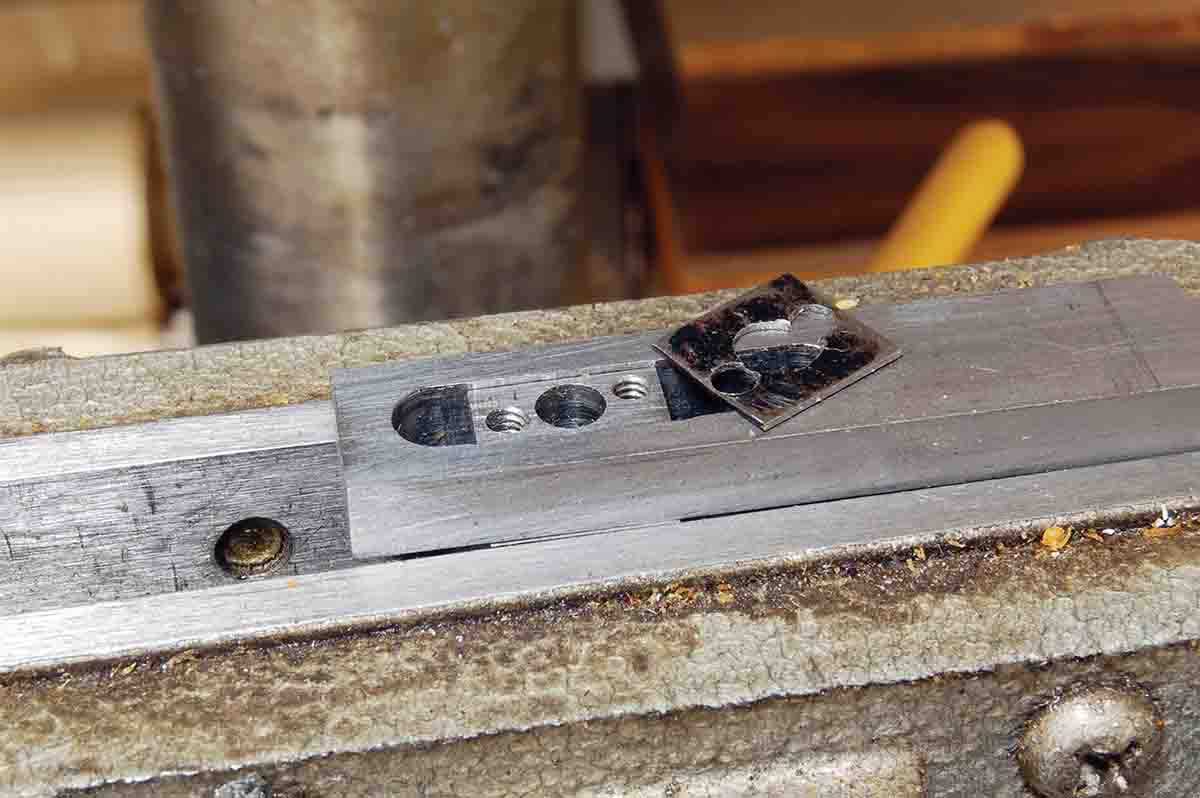
    The first part to make is the base, for which is used a piece of half-inch square tubing with one edge cut away. Length depends upon the spacing of the mounting holes in the tang. This tubing is available in 3-foot sections from home improvement stores. The center of the pivot hole for the staff is drilled .200 inch below the top center of the base. Sidewalls of the tubing are a bit thin to tap 6x32 tpi as on the previous sight, so 8x40 tpi was used here.

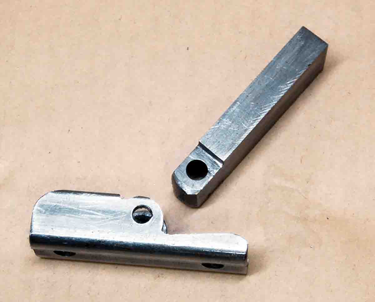
    The staff of the new sight is made from the same ½x¼-inch piece of cold rolled steel used for the first sight; however, almost no filing is necessary this time. After drilling the pivot hole in the staff material, file each side only enough to fit inside the base. Slip in the combination pivot/lock screw. The top edges of the base are now rounded only enough to allow the sight to move forward to sit vertically and fold back far enough to just touch the top of the tang.

    This is the setup to drill holes in the elevator that will be filled out to form an adjustment slot.
    This is the setup to drill holes in the elevator that will be filled out to form an adjustment slot.
    Next, lay a straightedge over the top of the open sights and measure down to the center of the distance between mounting holes in the tang. This gives the maximum height of the sight base/staff assembly. Trim off the top of the staff at this figure.

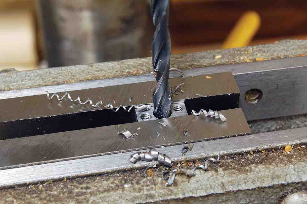
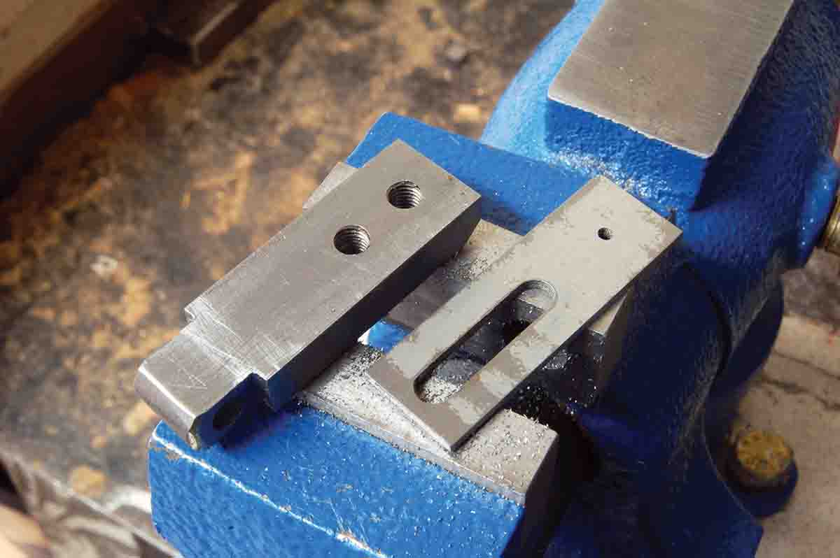
    Now comes the greatest simplification of this sight over the previous one. Instead of an elevator slider fitting in the sight staff, the aperture is just drilled in a flat piece of metal having a narrow slot cut in the lower center, allowing it to slide on the rear of the staff. Two screws fit the slot and lock the elevation. A photo shows this perfectly.

    Few dimensions have been given because they will vary depending upon the particular rifle, height of its open sights, tang height, etc. The elevator on my sight is .070-inch thick sheet metal. Lock screws are standard 8x40 tpi scope mount screws. The slot in the elevator is made by closely drilling holes of screw body diameter (No. 19 drill bit) that are connected by filing using a round needle file.

    A complete base staff with screw holes for the elevator (left) and the elevator with adjustment slot and aperture complete.
    A complete base staff with screw holes for the elevator (left) and the elevator with adjustment slot and aperture complete.

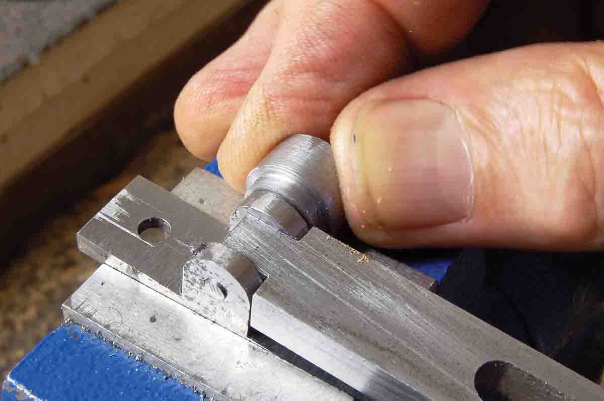
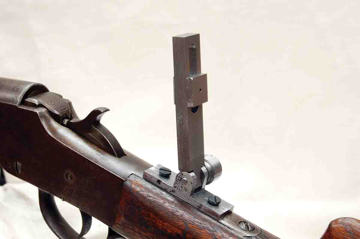
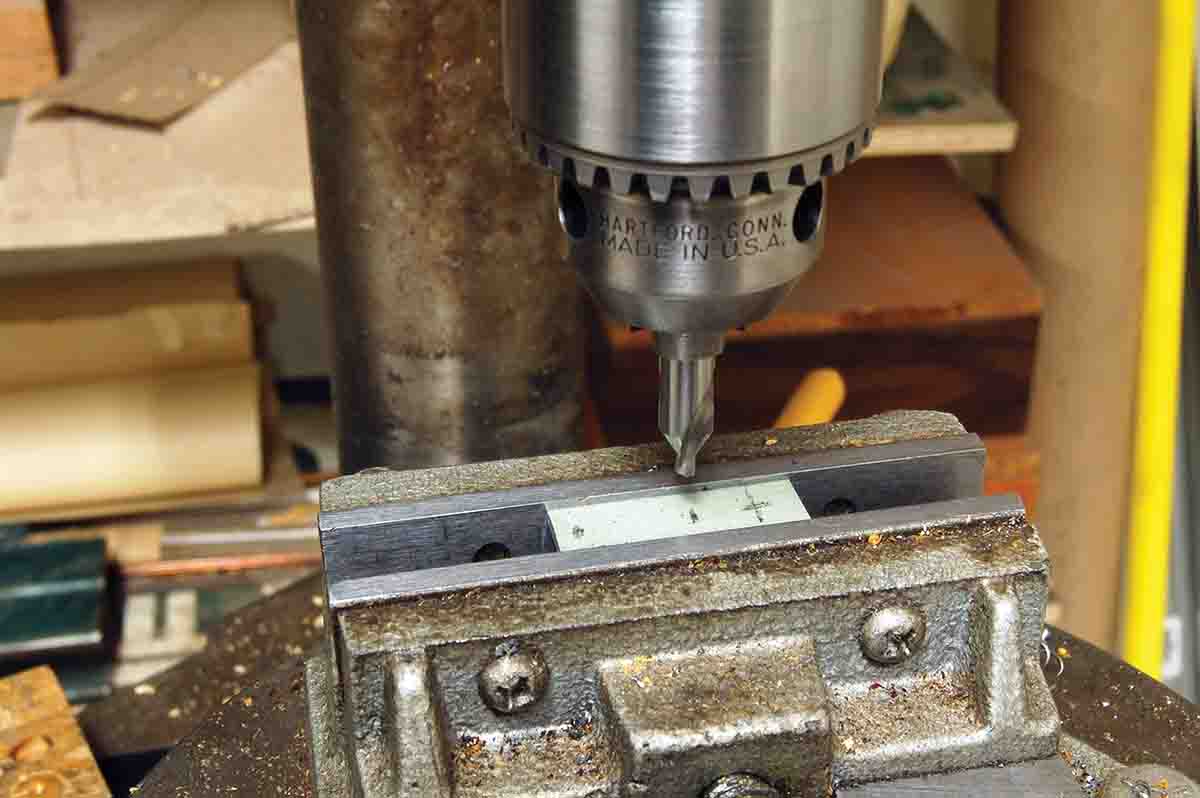
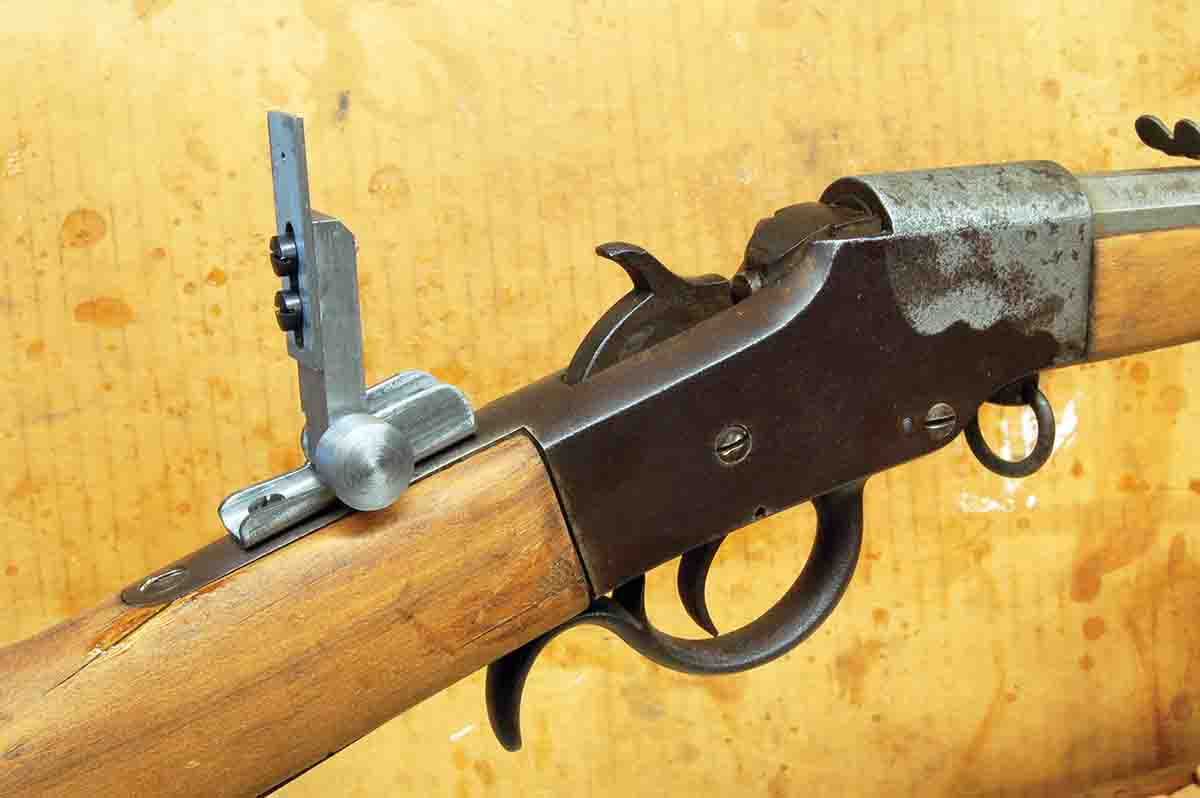
    Now a tip for drilling the tiny aperture (1⁄16-inch) where the large relief hole of the first sight made is not needed: Drill from the rear of the elevator, but first, lightly touch the sheet metal with a new ¼-inch drill. This produces a small depression that will prevent the tiny drill from walking, bending or breaking and ruining the whole day. A photo shows the complete sight on another Hopkins & Allen rimfire.

    A second sight complete and on another Hopkins & Allen rifle. Rounding sharp edges must be done here also.
    A second sight complete and on another Hopkins & Allen rifle. Rounding sharp edges must be done here also.
    Both of these sights have work yet to be done on them. Sharp corners and edges must be rounded off. There is no need to polish or remove file marks. Just rub with cold blue, then rub it off, matching the blue-gray or just gray finish of the rifle they were made for.

    Of course, making elevation adjustments is by trial and error, just like the originals. Windage is accomplished by shims under the sides of the base, just like the originals (or drift the front sight), but who cares? When properly used as described in the last column, sighting-in need only be done once.

    Spending time squirrel hunting or plinking pop cans or targets of opportunity then takes us back to a slower era – a time before the chatter of semiautos was upon the land; a time before money was plentiful; a time before we needed scopes (excuse me, optics) of a power that can discern the gender of a dragonfly at 200 yards. Also, neat, old rifles are both interesting and fun. Isn’t that really what brought most of us to rifle shooting in the first place?

    Wolfe Publishing Group