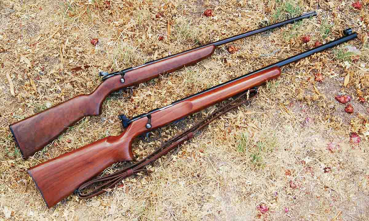
These are two of the most commonly seen rifles in the series: M510-P single shot (top) and M513T (bottom).
Most rimfire rifles are so darn reliable that little thought is given to anything more than pushing a patch through the bore and wiping off the blued surfaces if the gun resides in a humid environment. Unfortunately, just like people, time and lack of upkeep take its toll. Some .22s are more susceptible to this than others and the Remington 500 series is one of them.
Disassembly begins by removing the safety assembly that is held in the receiver by one screw.
In the late 1930s, Remington decided it needed a series of cheaper bolt-action rimfire rifles. This resulted in the M510 single shot, M511 clip-fed, M512 tubular magazine, M513T target, M521T target and a fancy M513S sporter. Economy was obtained by using the same receiver for all models. All had the same screw and pin holes, the same triggers, ears, safeties and ejectors. Bolts would also interchange between models, but the handles are longer on the target guns. Unfortunately, the bolt has two serious design flaws. More on this later.
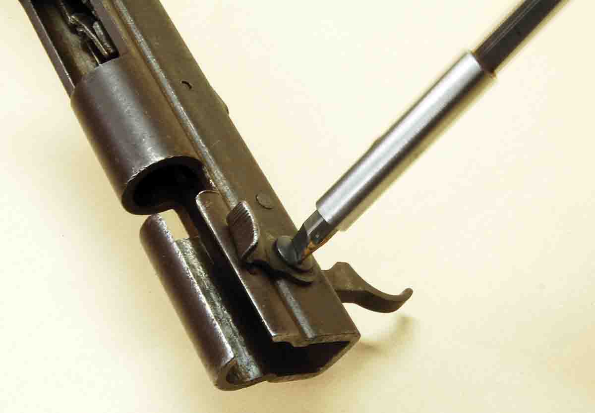
A spring and plunger in the trigger body (arrow) allow the safety to function. They must be removed to prevent loss.
Keeping the receiver body free from bugs, leaves and powder fouling is most important for the tube magazine model (see photos) because it can affect feeding. Removing the parts from the receiver of any of the models is the best way to do this. There is also a simpler, but less thorough method which will be covered.
To begin, slide the bolt out and then remove the stock from the barreled action. Looking into the open end of the receiver, the safety mechanism is front and center. It consists of three pieces: safety lever, safety screw and safety. Turn out the screw and remove the other two parts. There is a spring and plunger in the trigger that holds the safety in either “Safe” or “Fire” position. These must be lifted out or they may fall out and become lost.
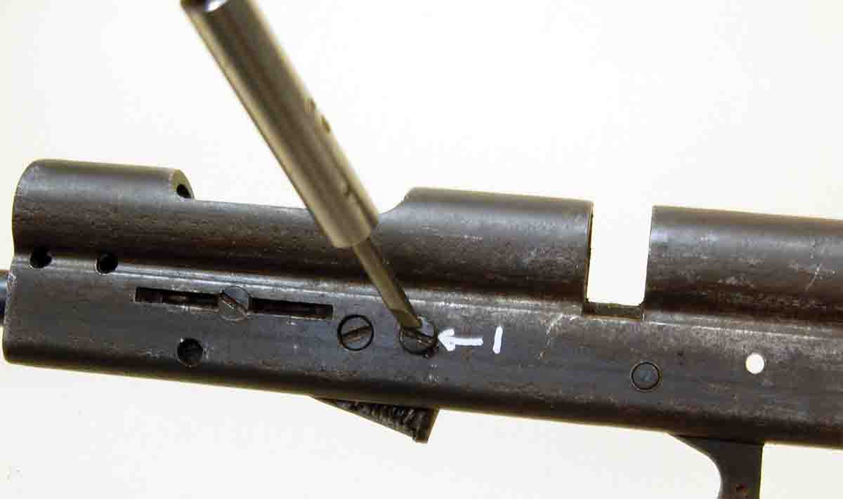
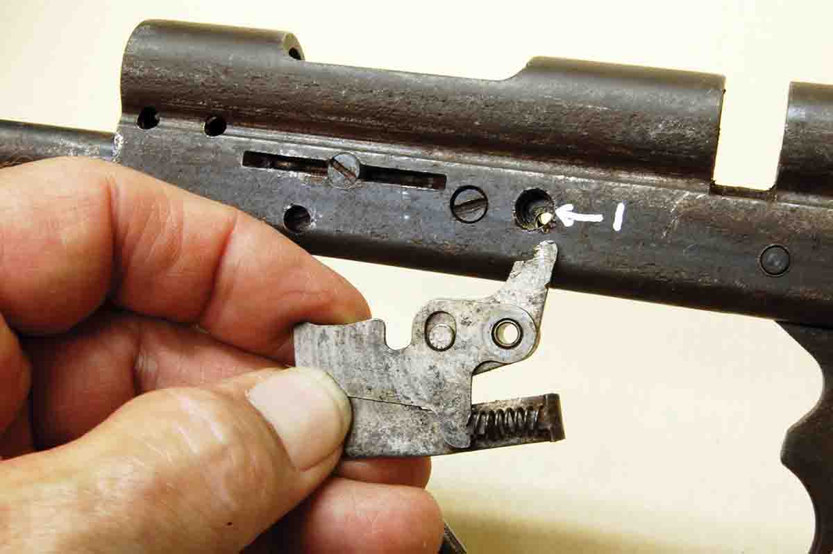
The screw marked “1” is removed to release the cartridge lifter assembly (tube magazine gun) and the trigger sear assembly.
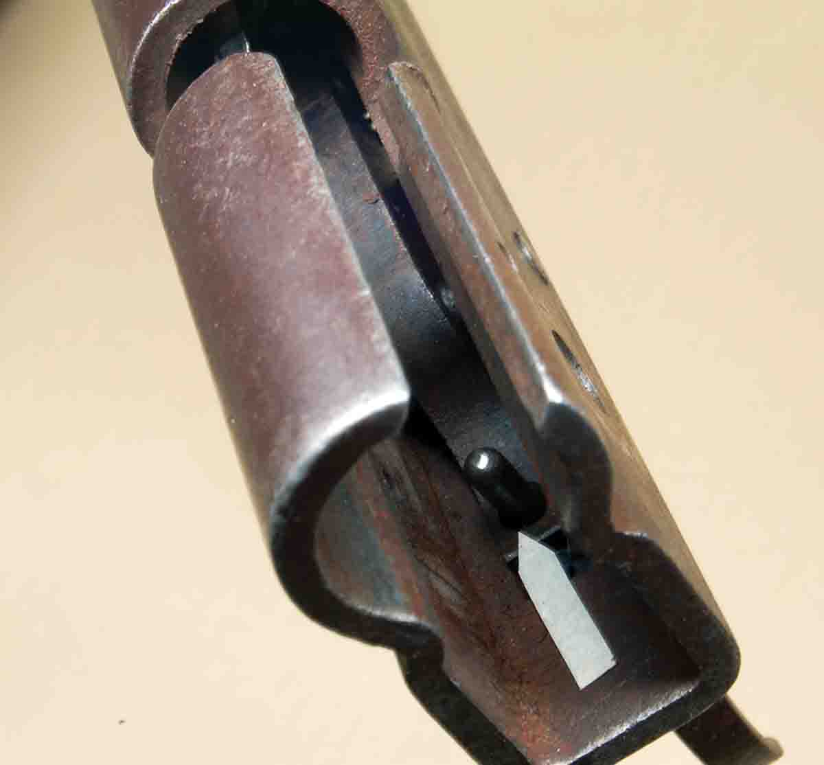
Removing screw “1” in the photo is next. It frees the cartridge lifter assembly and also passes through the trigger/sear assembly. The lifter assembly drops straight down out of the receiver. It consists of four parts: two of stamped sheet steel and a coil spring, all held together on a bushing. Push out the bushing, clean parts well, lube, reassemble the unit and drop in the parts tray until needed.
The cartridge lifter assembly drops straight down and out.
Next is the trigger/sear, which consists of two articulated parts connected by a tight-fitting pin. Do not remove the pin. The assembly is removed by driving out pin “2,” then pushing forward out the hole vacated by the lifter. This may appear impossible at first, but it will fall out when positioned just right.
The screw marked “3” secures the ejector, a very thin piece of steel. Threads are very fine. Removing the ejector is easy, but reinstalling it down inside the small receiver is a frustrating ordeal. A gentle touch is required or cross-threading will result. It is best not to remove the ejector.
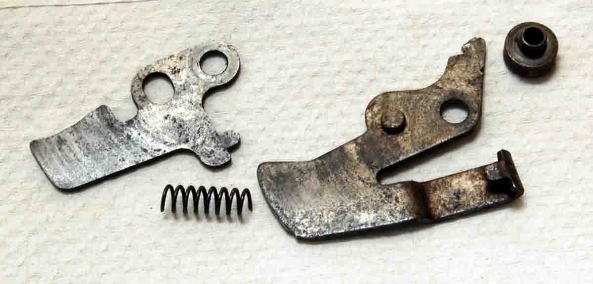
The lifter consists of three parts assembled on a bushing. Clean, lube and reassemble until needed.
The same applies to screws “4” and “5.” They secure small parts in the tube-feed mechanism. Both are set up hard, perhaps with a thread locker. It seems like they are not intended to be removed.
The last operations are to wipe out the receiver and push a bronze bore brush down the exterior magazine tube, followed by a lightly oiled patch. The interior magazine tube will now slide easily during loading.
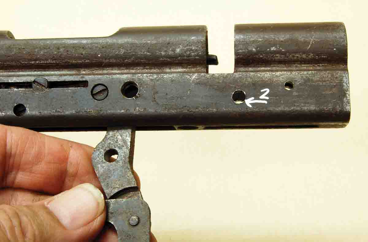
After driving out the pin marked “2,” trigger/sear assembly comes out the same hole as the lifter.
Now, we are supposed to say, “reassemble in reverse order.” However, the parts are free to slide around inside the small receiver. Holding them in place is difficult. Fortunately, another only slightly inferior procedure can be used to clean the inside of the receiver.
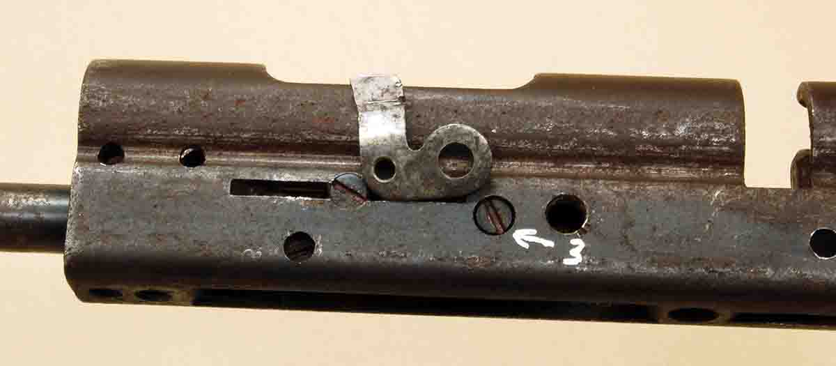
Screw “3” secures the ejector shown here lying next to the screw head.
The assembled receivers of all six rifles can be cleaned and lubed by what some call “spray and drain.” Hold the barreled action (bolt removed) by the muzzle and spray liberally with a solvent/degreaser intended for firearms. Anything else may damage small parts or remove bluing. After the solvent has evaporated, spray with one of the new “weapons lubricants” used by the AR-15 crowd. This should be sufficient for firing more ammunition than anyone can find!
Now we come to the bolt and its two major flaws. Both involve a single part that Remington called the bolt-handle assembly (consisting of bolt handle and cocking cam). The cocking cam portion is a hollow tube about an inch long with an outside diameter the same as the bolt body and the inside diameter only about .100 inch less. Two angled slots 180 degrees apart are cut in the rear half of this tube, while the front half holds two large integral locking lugs that fit into cuts in the frame. A small diameter pin (cocking pin) is driven tightly through the firing pin and protrudes out both sides, the ends of which ride against the angled slots. Finally, one locking lug is drilled to accept the end of the bolt handle, which is pressed and crimped in place – supposedly permanently.
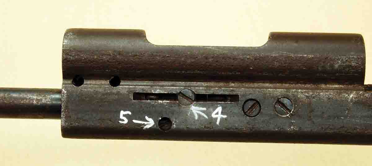
Screws “4” and “5” are set in very tightly, so they should not be removed simply to clean the inside of the receiver.
Raising the bolt handle causes the cocking pin to bear on the angled surfaces of the cam, pulling the pin backward and cocking the action. When the bolt is pushed forward, then down to lock, the sear drops into the sear notch in the firing pin and the gun is ready to fire. Sounds simple, but today, it’s a non-fixable problem waiting to happen.
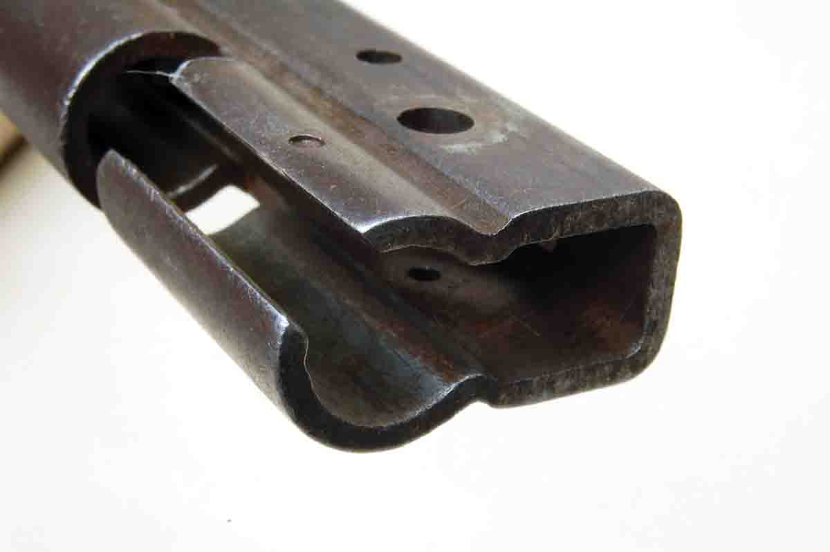
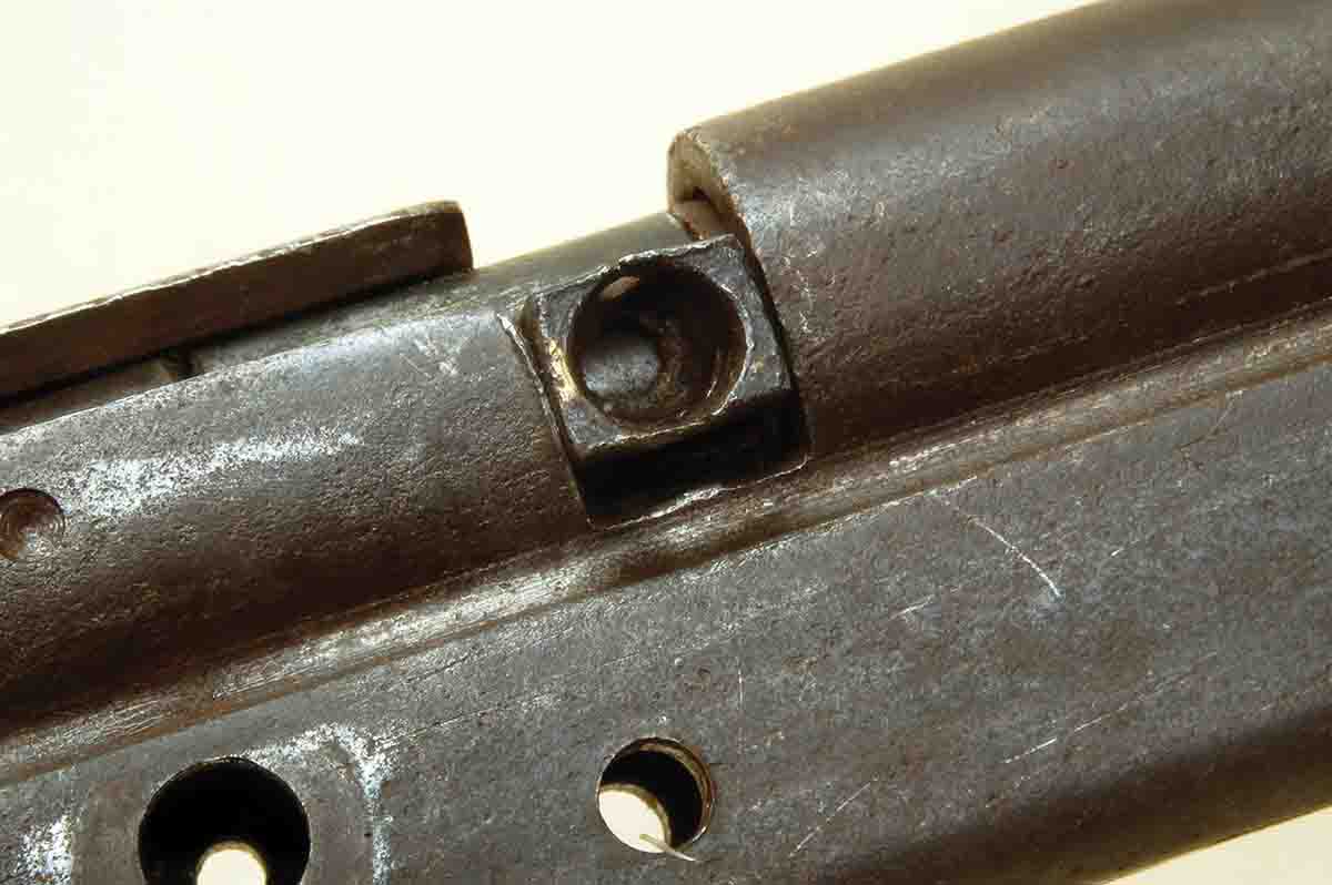
The rear view of the receiver shows the uniform wall thickness caused by the forming from seamless tubing.
The cocking pin is a piece of hardened drill rod. A cylinder holding the cocking surfaces, however, is case hardened. As gun folks know, case hardening is a surface hardening only a few thousandths-inch deep. With a round cocking pin and the surface it rides on only .050-inch wide and perfectly flat, contact between the two is minuscule. Cam surface begins to wear the first time the gun is cocked!
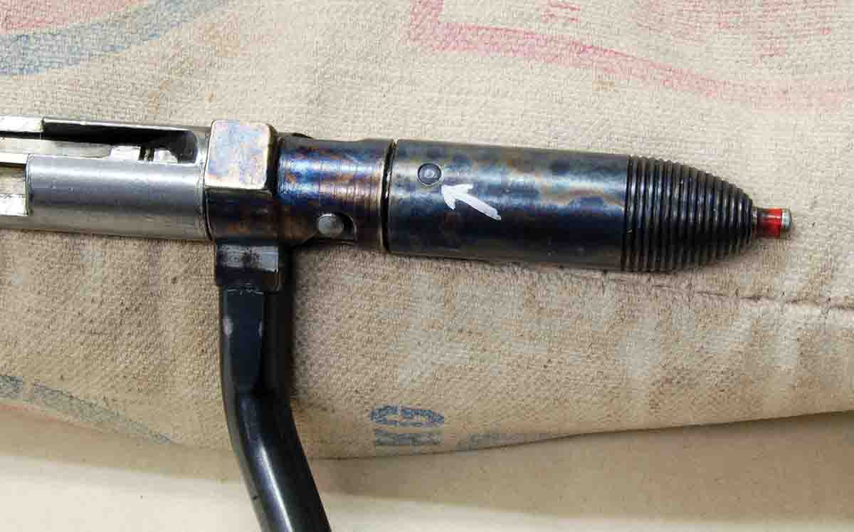
Driving out the pin allows for the removing the bolt shroud, mainspring and cocking indicator.
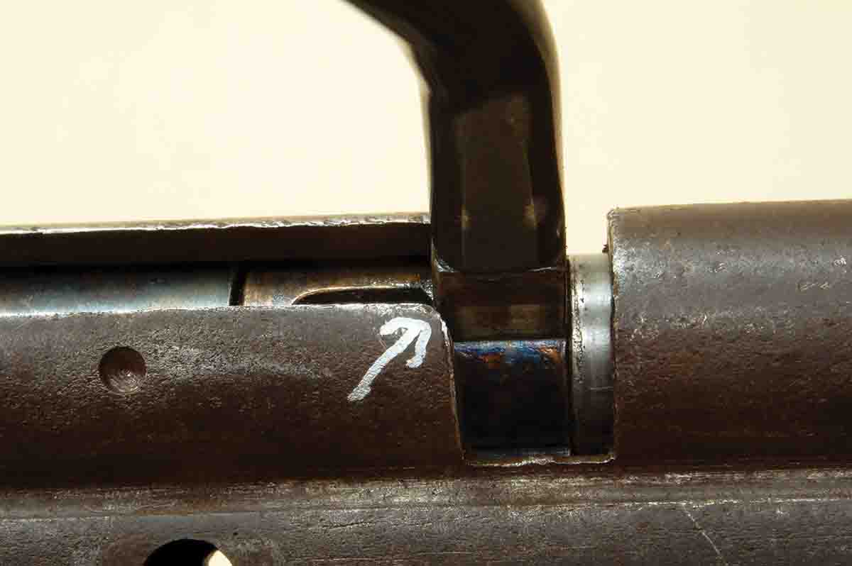
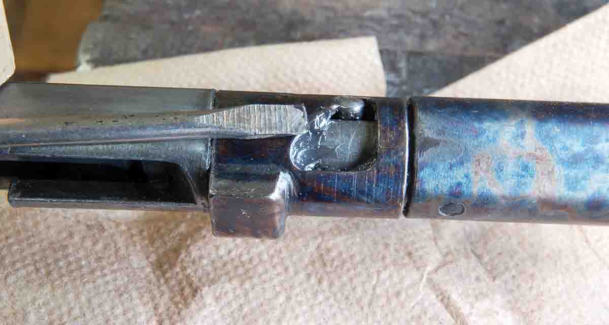
Photos show the worst wear I have ever seen on a cocking surface, but the cocking pin is not worn at all. Usually, the ridges of rolled-up metal can only be detected by rubbing with a fingernail. What this wear looks like is not important, it’s what it does.
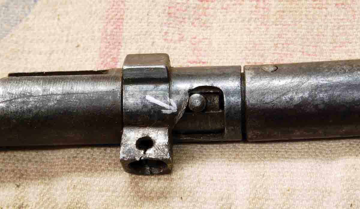
This is the worst wear Gil has ever seen on a 500-series cocking notch. Note the metal rolled up in front of the cocking pin (arrow). Also, note the missing bolt handle.
Worn-through case hardening means more force is needed on the bolt to cock the action. It also means that the firing pin is coming back a few thousandths of an inch less than when new. Wear soon causes the sear to drop into the sear notch just a bit before the bolt goes far enough forward to turn down into its locking recess. It is then necessary to push even harder on the bolt handle. I essentially have a cock-on-closing action for the last small amount of bolt travel, which gradually gets worse with time. Soon, the extra force causes the pressed-in bolt handle to loosen in its joint with the locking lug. Eventually, the handle comes off.
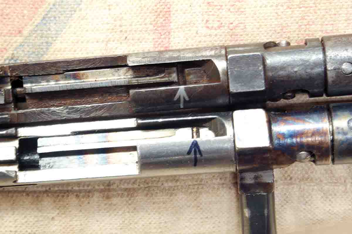
The sear notch in the firing pin is farther forward on the top bolt having worn the cocking surfaces. The bottom bolt is nearly new.
This problem would be simple to solve by just driving out a couple of pins and replacing the bolt handle assembly, but these guns were discontinued in the 1960s. A new part is not available and its complexity is such that it can’t be simply welded-up or turned on a lathe.
The best that can be done for guns that haven’t been shot enough that the wear is still preventable is to lube the angled cocking surfaces with a heavy-duty molybdenum disulfide wheel bearing grease. I use Sta-Lube brand. This seems to prevent wear (or at least minimize it) on the case hardened surface; regular oil doesn’t. It’s really an unfortunate situation, but with proper cleaning and lubrication, many of these rifles can be kept shooting for years to come.
When the sear drops into the sear notch early in the worn bolt, the handle won’t go far enough forward (arrow) to go down into the locked position. It must be forced.
The handle came off this bolt due to pressure caused by cocking surface wear.
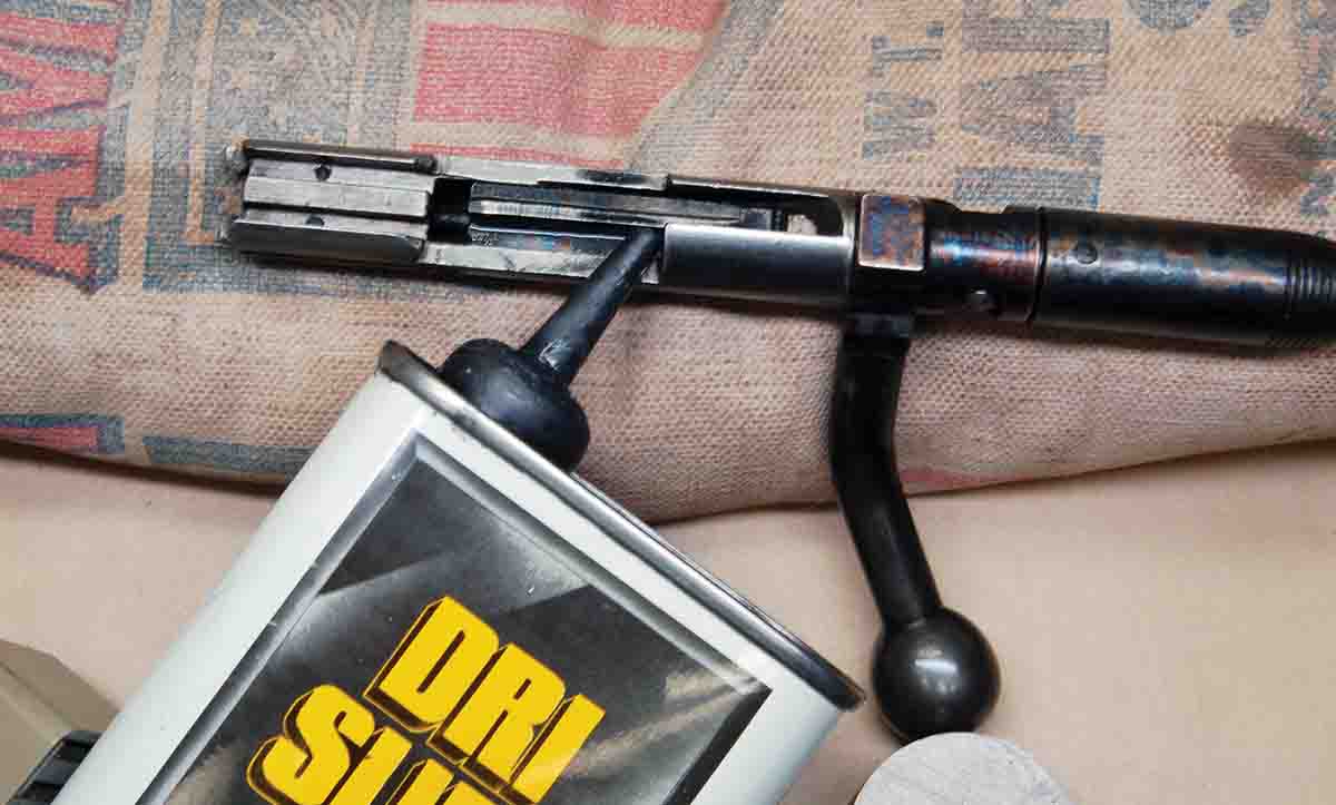
The bolt need not be disassembled to lubricate. Just add a couple drops of dry lube every few years.
The most important thing to do for any 500-series rifle is lube the cocking surfaces with molybdenum disulfide grease.