
Light Gunsmithing
Ruger 10/22 Magazine Improvement
column By: Gil Sengel | January, 19
Today the tubular magazine is pretty much gone, replaced by the ubiquitous detachable box magazine that many folks call a “clip.” Almost without exception, they are stamped, soft, sheet metal or plastic creations. Not only do they wear, but if dropped the feed lips or body will be dented. Reliable feeding can be a thing of the past.
When Ruger’s 10/22 came on the scene in 1965, everything changed. The Ruger detachable box contains a rotor similar to the centerfire Mannlicher-Schönauer and Savage M99. Made of a proprietary General Electric Corp. product called Celcon that is tough as grizzly bear toenails, and featuring a cast steel throat, the magazine is nearly indestructible. It’s also dead reliable. There are, however, two problems often noted by hunters.
The first is the rifle’s failure to lock the bolt open after the last round is fired. Making this happen would require modifications to both magazine and rifle. Doing so would add cost, so it won’t happen. The second item is the subject of this column: Being able to know at a glance how many rounds are in the magazine.
Old five-shot metal magazines had to be refilled each time the rifle was fired at game to prevent running out of ammunition at the next opportunity. Doing so requires laying the rifle down on the ground or leaning it against a tree, removing gloves and picking a couple of the tiny cartridges out of those annoying plastic boxes. It is a noisy two-hand operation that is undesirable if targets are scurrying about. Ruger’s 10-round magazine greatly reduces the frequency of such fun, but if one cartridge remains in the magazine there is no way to know how many more (if any) remain.
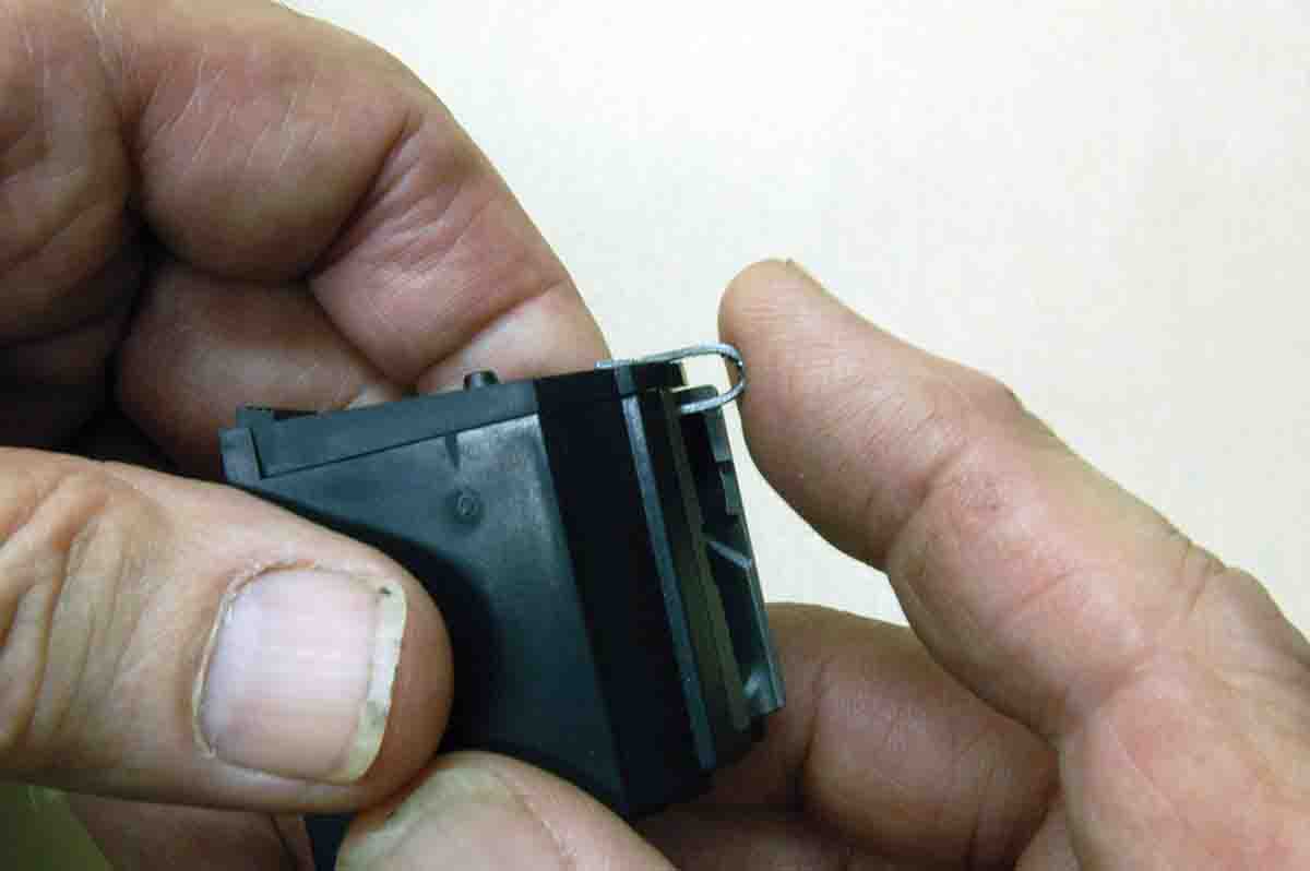
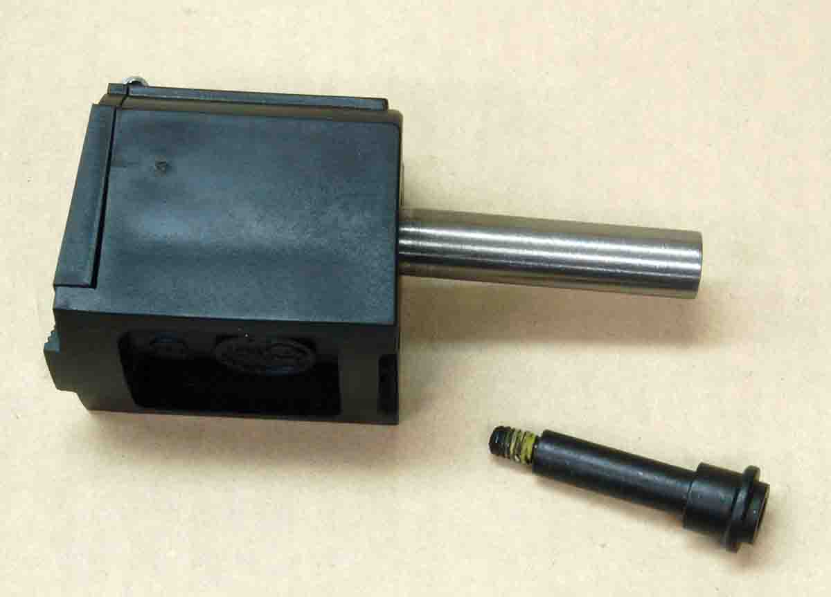
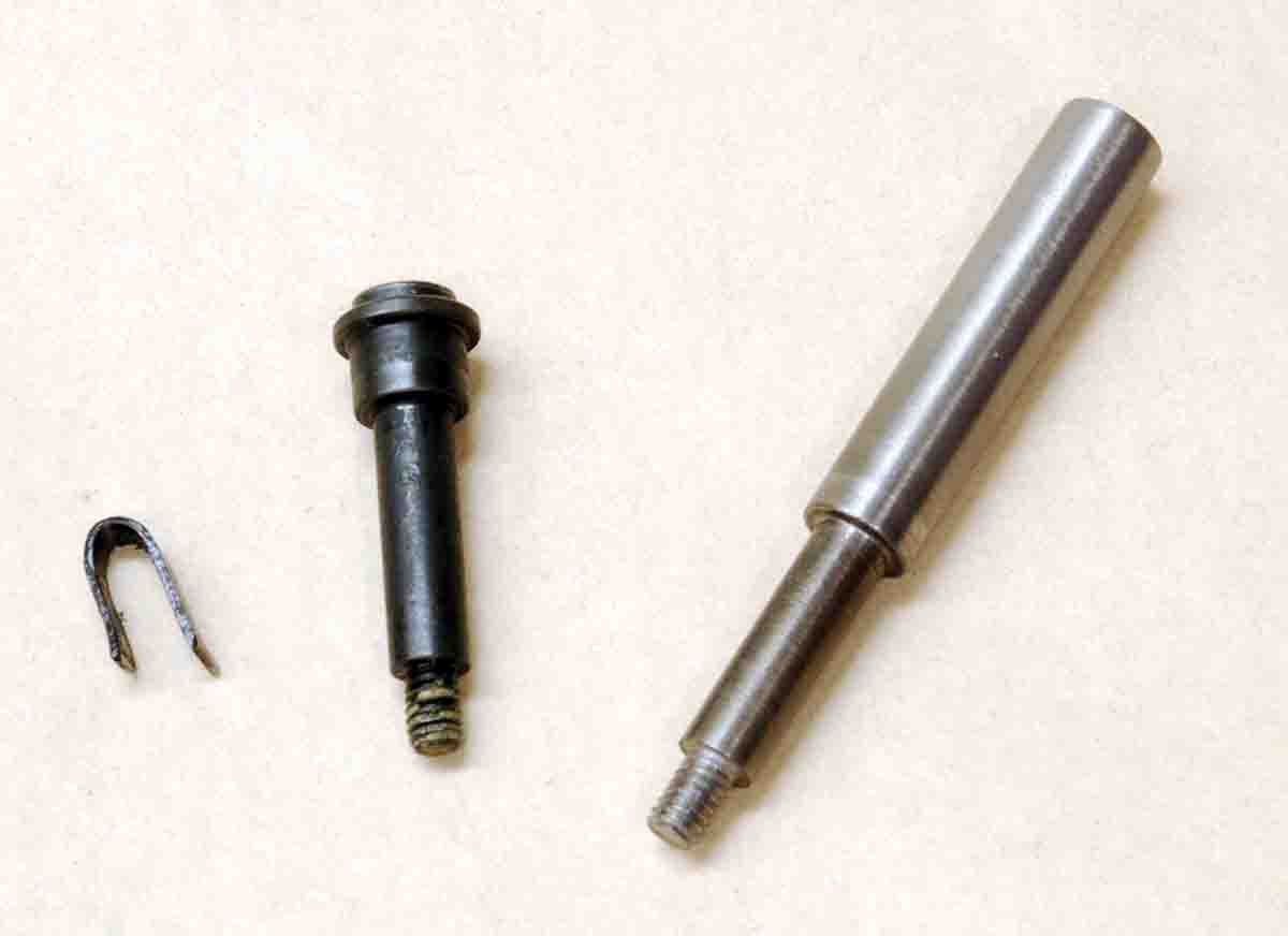
To alter a 10/22 magazine, it is first necessary to disassemble it. In Rifle No. 280 (May 2015) this is explained in a bit more detail, but it’s quite simple and shown in the photos. A U-clip is made from .030-inch-thick sheet metal. There are no critical dimensions here; just make it fit tight, because it holds the magazine throat in place when the body is removed. An axle screw must also be made to copy the factory screw without its head. This allows the magazine body to slide off, leaving the rest of the parts locked in place. Be sure to keep a fingertip over the axle nut when removing the factory screw and installing the headless one, so rotor spring tension is not lost.
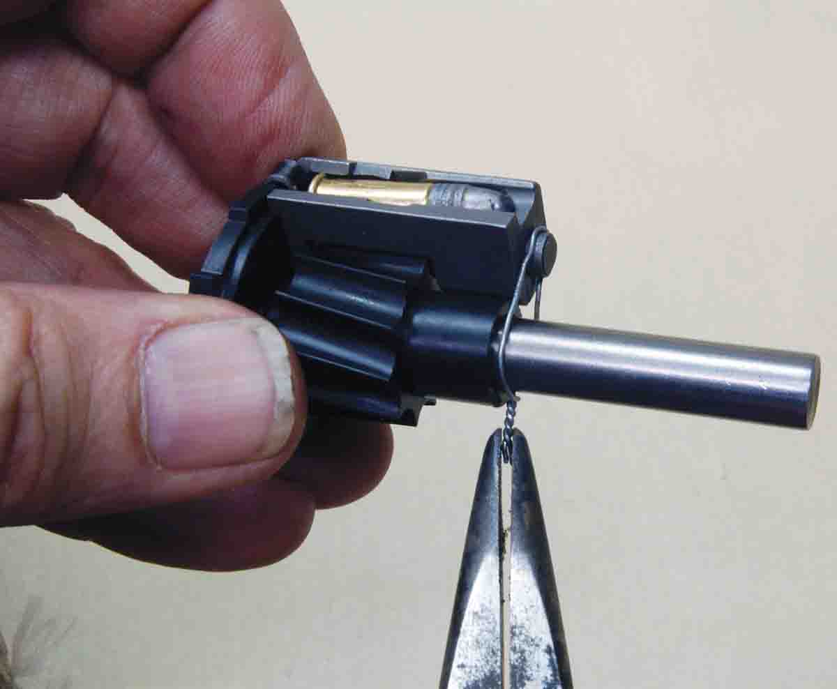
At this point, if the U-clip is not quite strong enough or the rotor spring is too strong, the front of the magazine throat may not be resting on the cylindrical front of the rotor. It must touch here, so simply wire it down as shown in the photo.
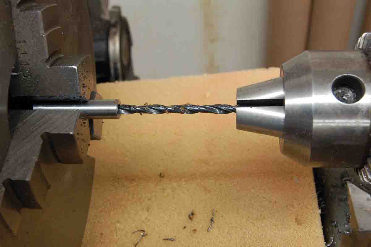
A final item to make is a drill guide. This is a 1.5-inch piece of a 1⁄4-inch drill rod with a 1⁄8-inch hole drilled through it. The hole’s diameter was picked because it is the shank diameter of Dremel tool accessories. It is much easier to control a Dremel tool than a full-size electric drill when drilling through the back of the magazine.
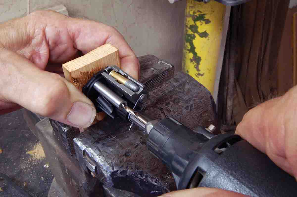
The drill guide is placed over the drill, then it is laid in the cartridge groove next to the magazine throat. It is tempting to now drill through the magazine back and move on to the next rotor groove. Don’t do it. Even though cartridges are perpendicular to the rear of the magazine when pushed in, they are moved well out of line by the rotor. This is necessary to assure the rim of the round on top is always in front of the round below it, thus allowing the top cartridge to strip cleanly from the magazine and not hang-up on the lower round’s rim.
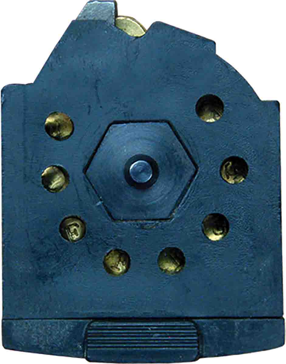
The back of the magazine is quite thick, so drilling at this angle will result in a hole that is far out of line on its outside surface. To correct this, allow the drill guide to lay in the rotor groove only at the very rear. Lift the front of the guide until it is perpendicular to the magazine back plate. Drill this hole and continue around the rotor. Note that only eight holes can be drilled because the second cartridge location in the magazine is blocked by the steel magazine throat.
The plastic is easily drilled despite its toughness, so holding the magazine in one hand may seem logical. However, a backer board should be used. The board has a small hole drilled in it to accept the protruding axle nut, thus allowing the magazine to fit flat and solidly on the board, protecting your hand at the same time. Use the backer board.
Drilling needs to be done on a drill press with a depth stop so the drill just passes through the magazine back and does not go in far enough to damage the rotor. Don’t worry about chips falling into the magazine as a sharp drill brings the plastic out in two long, unbroken spirals.
Yes, drilling the 10/22 magazine seems a bit involved, but not for anyone who enjoys working on long guns. Hunters will wonder how they ever got along with factory magazines. Ruger 77/22s use the same magazine, and there are probably more of them in the woods than 10/22s!