Light Gunsmithing
Maintaining Winchester’s Later Model 52
column By: Gil Sengel | May, 23
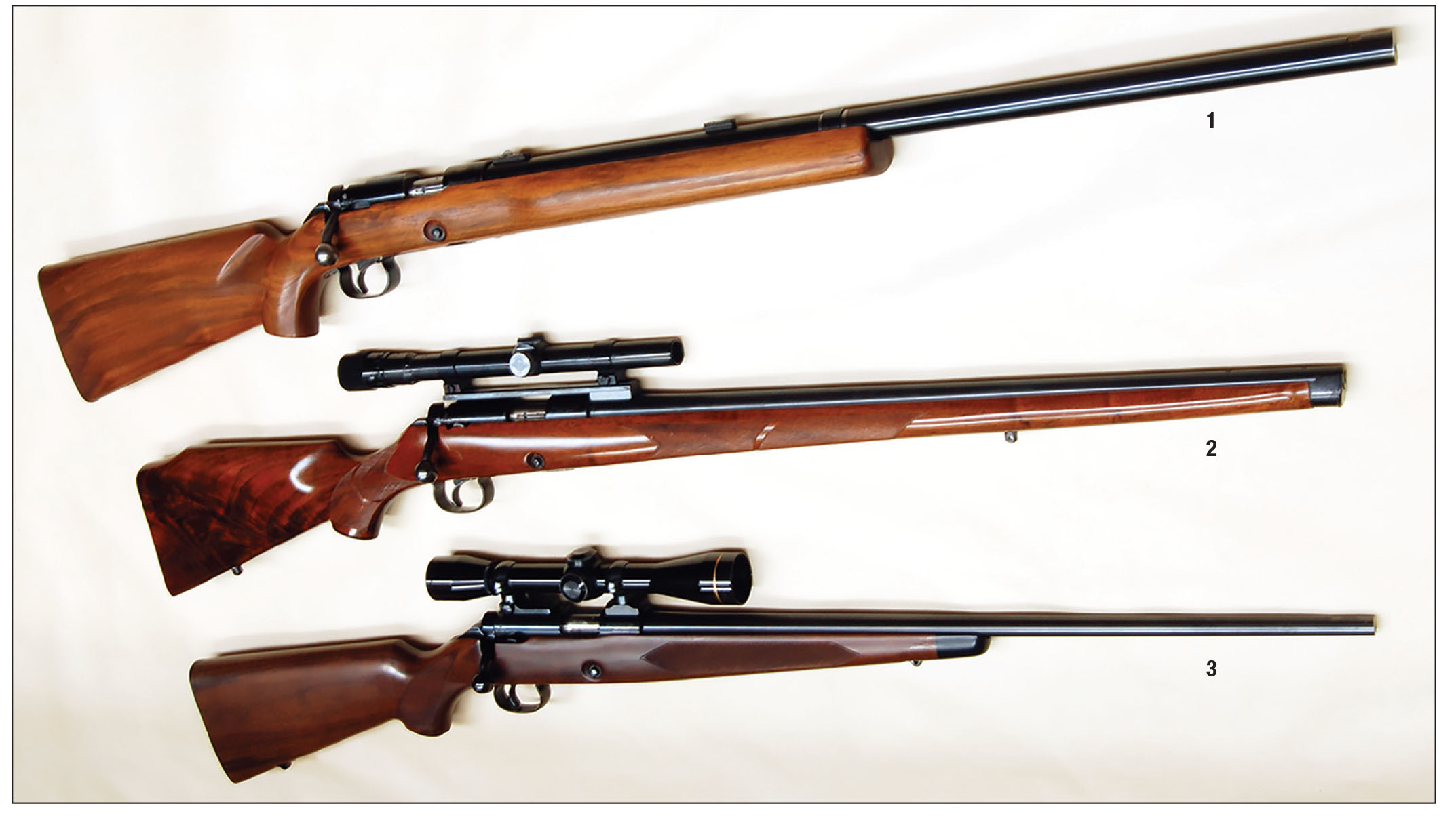
In my last Rifle column, I covered Winchester Model 52 rifles up to the 52B and its supposed trigger problems. Some complained that the trigger “kicked back” (finger piece snapped forward) when the sear released and had “annoying vibrations” when the rifle fired. There was, however, a problem with the problem – Winchester engineers could not duplicate it! It’s pretty difficult to correct a mechanical problem if the complaint can’t be experienced by the person tasked with correcting it. Many small changes were tried, but still some owners were unhappy. Could this have been an early example of “fake news” at Winchester’s expense?
Since Winchester couldn’t find anything wrong with the Model 52B trigger, when factory-adjusted, the company stuck with it. This soon began costing Winchester sales. Then, World War II shut down all sporting arms manufacturing.
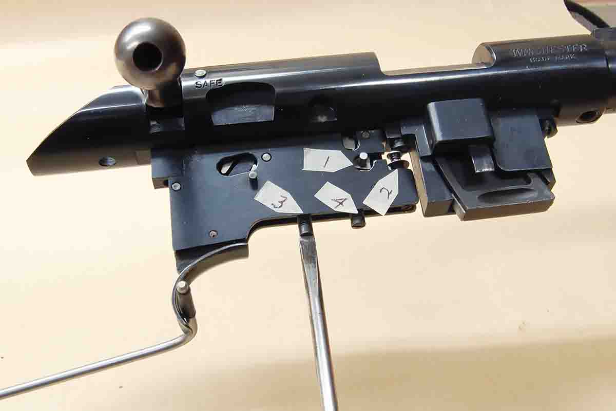
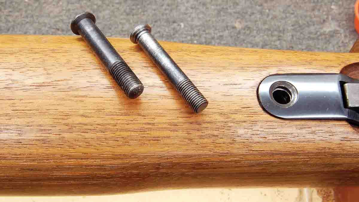
The result of all this was the July 1951 announcement of the Winchester Model 52C with its new Micro-Motion trigger. The outward appearance of the rifle didn’t change much. However, the trigger was a whole “nother animal” as the farmers, assembly line workers and their offspring that I shot with in the early 1960s called anything new “mysterious.” Gone was the old “open trigger” where all parts were assessable for cleaning, lubing and tinkering with springs. In its place were two 3x1.5-inch steel plates ground to .080-inch thickness. These were held together by rivets passing through steel spacers. All parts, springs and pins were assembled inside this housing. A large pin at the front and a machine screw at the rear held the housing to the receiver. There was no looseness anywhere.
single-shot action, the movement of the trigger of .003 to .005 inch releases the firing pin. The only way normal shooters know this has happened is when they hear the report of the shot.
Given the excellence of the Micro-Motion trigger, it is logical to ask how to disassemble it for cleaning and lubrication. The simple answer is – don’t! While the trigger is not all that complex, pins are staked in place. Driving them out could cause damage to parts and small springs. Pushing out all the pins and shaking out the parts would pretty much guarantee that the trigger never worked again. Multi-lever triggers are meant to work dry. Levers are reset by weak springs that will not do their jobs if even slightly bent. One drop of oil on their levers or pins can cause enough resistance to prevent resetting. Removing gummed-up or hardened oil without damaging something would be difficult. The Winchester parts department sold the Micro-Motion trigger housing complete with all parts factory-adjusted. You can bet there was a reason for that!
Properly adjusting a Micro-Motion trigger is not difficult. However, it is a well-known trait of the human male to be unable to pass an adjustment screw without turning it, if for no other reason than just to see what happens. Indiscriminately turning the three screws will cause things to happen, but nothing on the list will be desirable!
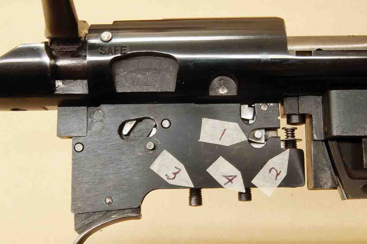
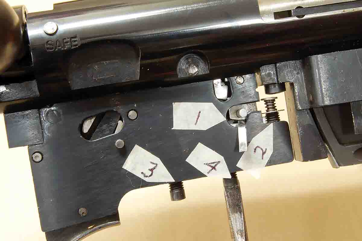
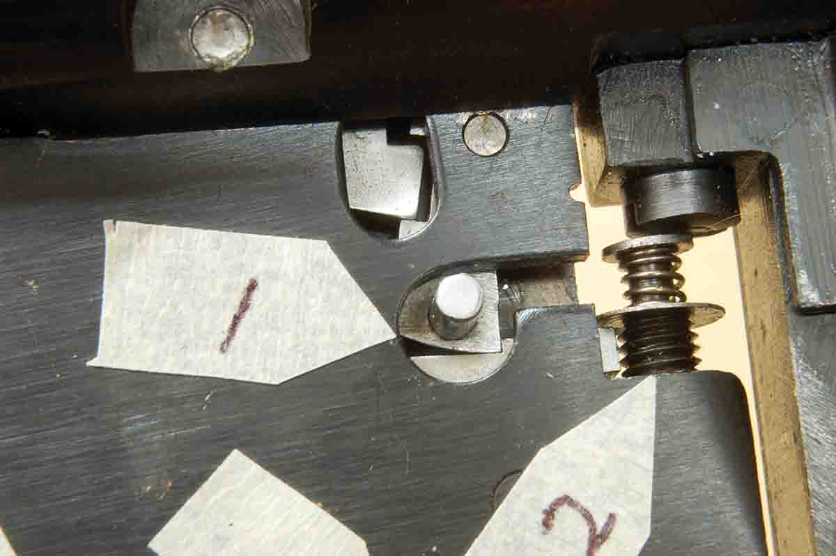
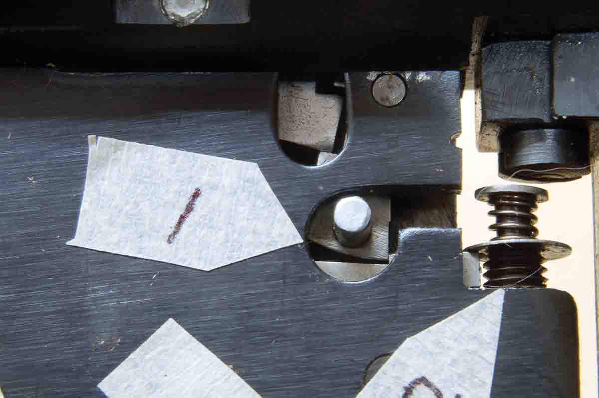
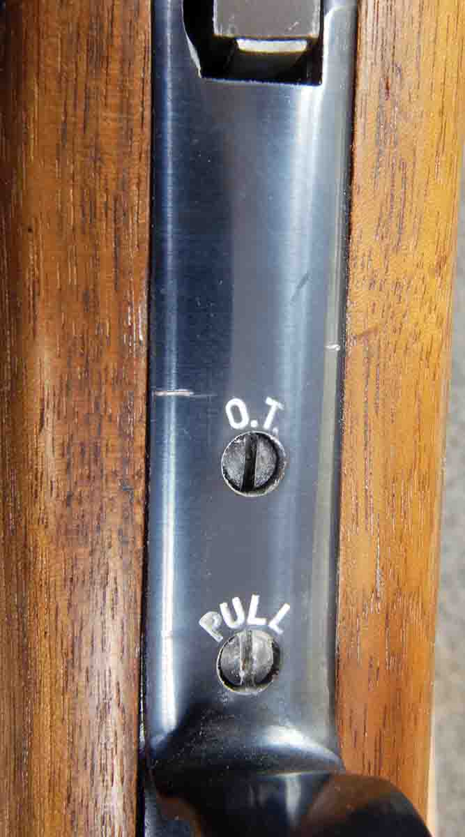
Begin by setting overtravel. For a Micro-Motion trigger, this only needs to be done once in a lifetime. The adjustment screw should never have been accessible on the outside of the rifle. At any rate, remove the barreled action from the stock. Clamp the barrel in padded vise jaws so that the right side of the trigger housing is facing up. A photo shows the two lever surfaces that separate when the trigger is pulled, releasing the firing pin. (Note the safety lever and its spring have been removed by the rifle’s owner.) The mechanism is cocked and has full engagement depth. Now, snap the lock and note how the bottom lever has moved down out of engagement. The top lever has moved forward and rests on top of the end of the bottom lever. Pulling the trigger will cause the bottom lever to move down out of contact with the top lever. The amount of space between the two is overtravel. Another photo shows a .015-inch shim inserted in this space with the trigger held back. The screw marked “O.T.” is now turned clockwise until the shim will just fit in the gap. Overtravel is now set forever. The other adjustments do not affect it. The pull weight will mask this tiny amount of movement.
The pull weight is last. These figures don’t seem to show up in Winchester ads, but the review of the new Model 52C in the September 1951, issue of American Rifleman stated, “The weight of trigger pull can be changed from 2½ pounds to 6 pounds…” Written by General J.S. Hatcher, he should have known better. The Model 52C was intended to compete in world-class events. If the trigger wouldn’t function below 2.5 pounds, Winchester might as well have stopped producing rifles and started making golf clubs.
There is only enough space left to say that the bolt and receiver of the Model 52C is essentially the same as the Model 52B, thus lubrication can be done in the same way. The oil option should not be used, however, because the Micro-Motion trigger is open on top and oil could work its way into the mechanism.
Next time, I will deal with the mystery of removing the bolt (and putting it back), the Model 52C Sporters and bore cleaning to improve accuracy.