Spotting Scope
Determining Pressure
column By: Dave Scovill | September, 18
In general terms, as the bullet is seated out, case capacity increases and barrel length decreases. Conversely, as the bullet is seated deeper, case capacity decreases while barrel length increases.
Seating depth, as measured in terms of distance from the bullet to the lands in the barrel, also has an effect on pressure, or if you prefer, the overall loaded length. Most SAAMI standards for chamber dimensions are consistent from one manufacturer to the next, but chamber design for the 7x57mm was changed back in the 1980s, reducing the military .5-inch throat length to approximately .25 inch. Another exception to SAAMI standards often occurs with Weatherby cartridges, where industry standard chamber design includes a freebore that allows up to .5 inch of bullet travel before it engages the lands. Custom chambers, however, often eliminate the freebore, so bullets must be seated deeper and powder charges reduced accordingly.
Of course, bullet designs, including cup-and-core, monolithic solids, plastic tips and boat-tails, all have an effect on bullet length. Where some bullets are longer than others in the same caliber and weight, seating depth varies, mostly in the interest of maintaining recommended overall loaded length, which in turn has an effect on case capacity under the bullet. Additionally, all other factors being equal, a bullet that is seated close to or on the lands generally produces an increase in chamber pressure when compared to the same bullet that is seated off the lands.
We also know case capacity can vary from one brand of brass to the next, and different primer brands can be expected to have an effect on pressure, along with different lots of the same powder. None of the above is to ignore the effect different barrels from the same or different manufacturers may have on pressure.
The catch is that folks may be using a different bullet than is listed in the manual or a different brand of case or primer – the sum of which calls for additional caution. In addition, most loading manuals show a custom barrel was used to develop loads listed in the tables, which sort of throws all the data listed into a cocked hat when using an off-the-shelf rifle that is one of hundreds, or thousands, produced by the manufacturer.
The solution for many years appears to have been vested in the art of reading pressure signs. That is, assessing exterior primer and case condition and noting the amount of effort required to turn the bolt or open the action on a fired cartridge. The latter required working up loads and watching for external signs, such as flattened primers or case condition until extraction became a bit “sticky,” then backing off one or two grains. All of which may have been fired in the same or different cases, which was left to anyone’s best guess, assuming folks were aware that it makes a difference.
At any rate, all or most of the above represent the mind-boggling maze that novice handloaders walk into. I got around it in the mid-1950s by staying away from maximum loads, which was reinforced by the fact that pushing for an additional 50 or even 100 fps was a little silly considering deer didn’t seem to care if the velocity of a 117-grain slug was 2,400 or 2,600 fps. When the bullet was placed properly, they fell over, or if they ran at all it was a short distance. Of course, in later years it was obvious that there was little need for a so-called “magnum” if it wasn’t utilized to its fullest capacity. Even then, if a load shot well with a 150-grain bullet loafing along at 2,950 fps, there was little need to reach for 3,000 fps. Ballistic tables proved that by showing less than one-inch flatter trajectory for the faster load at 300 yards or so.
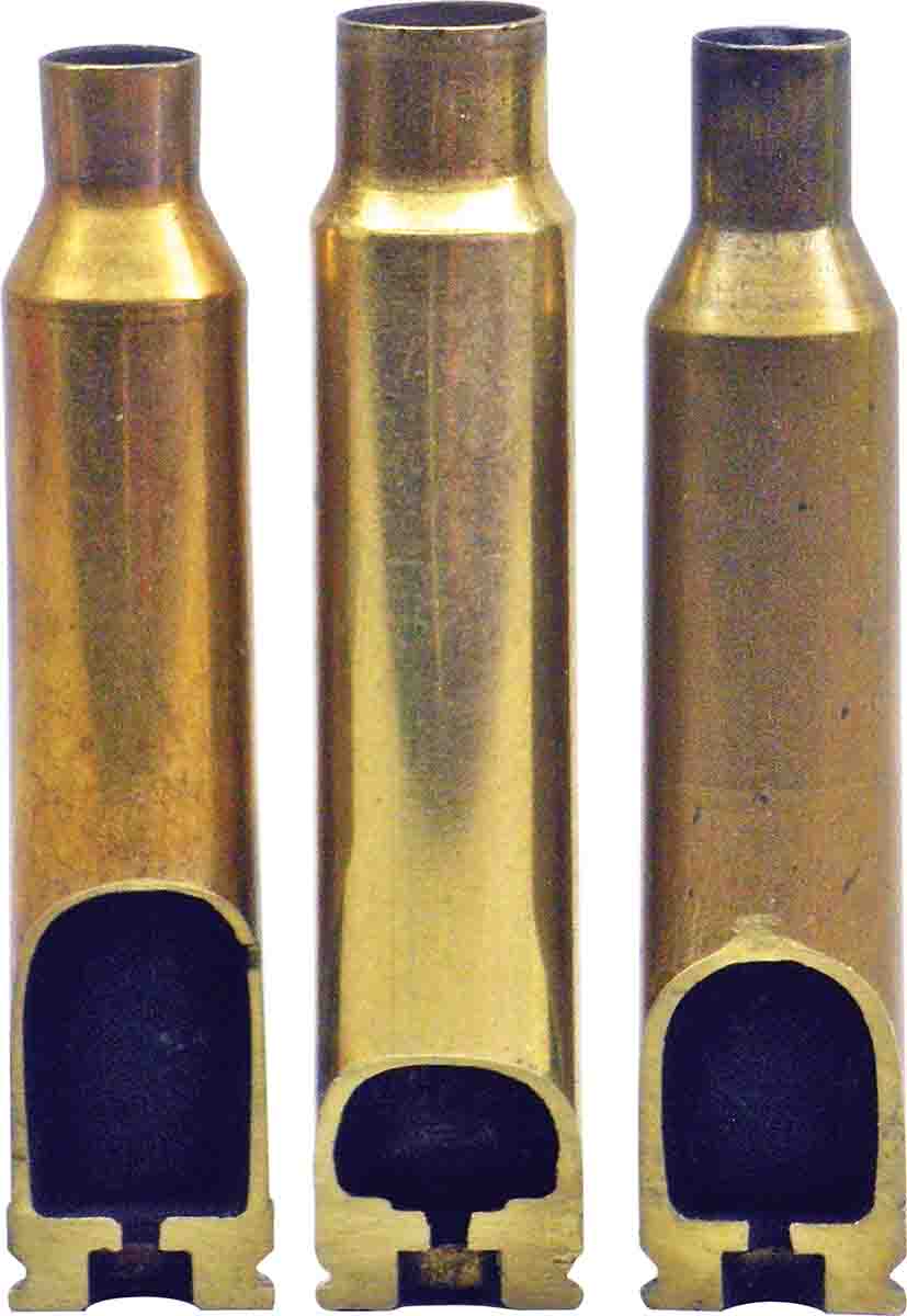
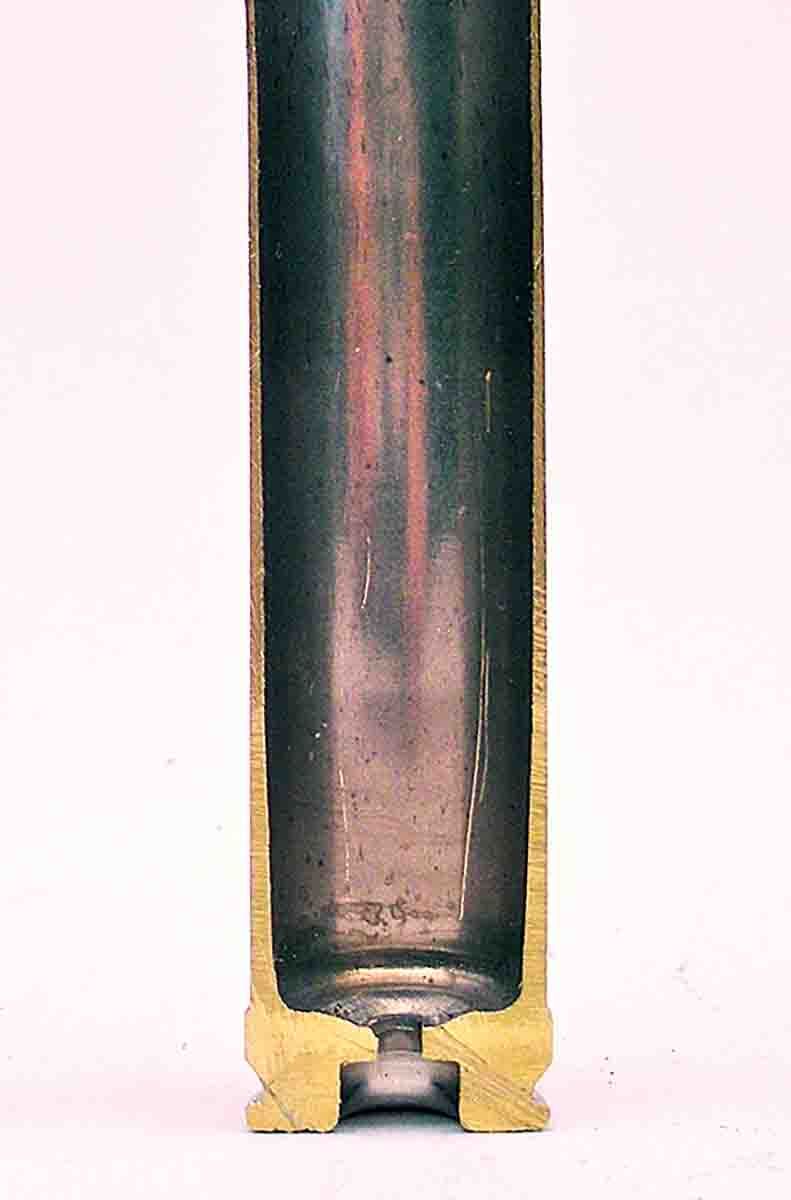
To stay out of trouble when working up toward maximum loads, it makes sense to measure case head expansion – as measured at the front edge of the extractor groove with a rimless case or on the belt of belted rimless cases – and compare those numbers to expansion measured on factory loads. This helps prevent excessive case stretching, sticky extraction, flattened primers and to avoid loose primer pockets if cases are used repeatedly. When working with wildcats or standard cartridges with new or untried bullets, such as the Barnes TSX, where there was no published data when they were first introduced, measuring case heads before and after firing was necessary, since there were no guidelines to follow, save for data for a bullet of similar weight and, hopefully, design.
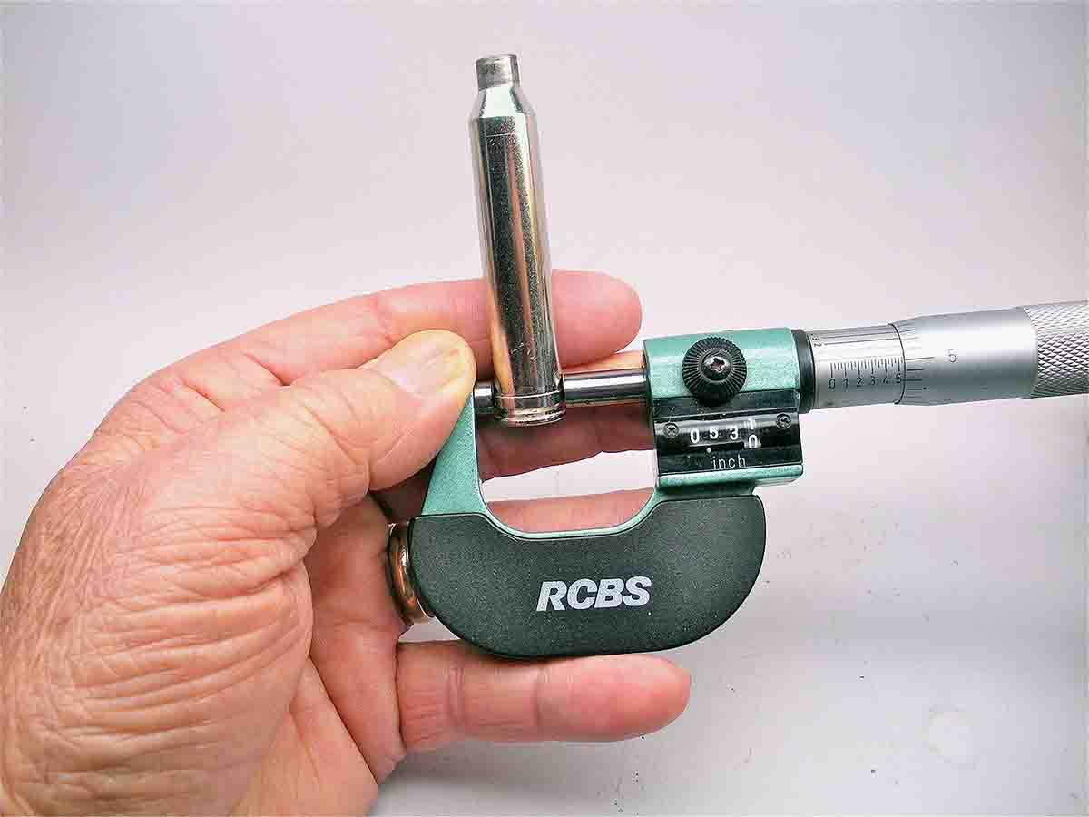
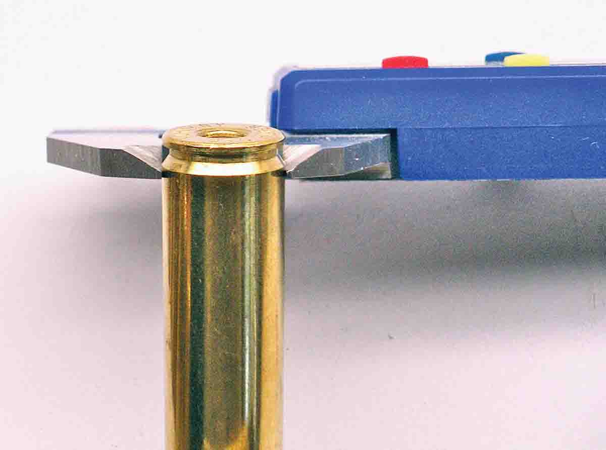
The procedure as outlined by Ken Waters and Bob Hagel in and Handloader magazines required a blade dial micrometer, measuring an unfired case before and after firing, being careful to not force the caliper beyond initial contact with the surface of the case, and being consistent. Measure twice, 90 degrees around the circumference. For a belted case, accepted expansion is .0005 inch. For a rimless case, hold the line at no more than .0006 inch. Work with the .30-375 Ruger wildcat indicates a maximum of .0005 inch case head expansion appears close enough, validating pressures and velocities that place it between the .300 Winchester and Weatherby Magnums.
Using a digital micrometer with a larger measuring surface, the case rim may be the same diameter as the head just ahead of the extractor groove, and usually is. In an effort to keep the measuring surface off the web of the case, this may cause the .25-inch diameter measuring surface to read off the rim, giving a false reading. The solution is to file the rim down slightly, twice, 180 degrees from each other, to make sure the rim is smaller in diameter on the flats than the case head, being careful to keep the file off the case head.
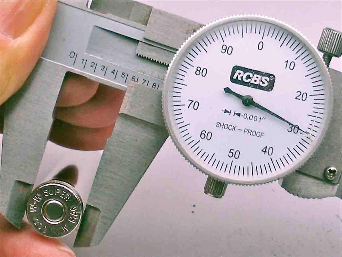
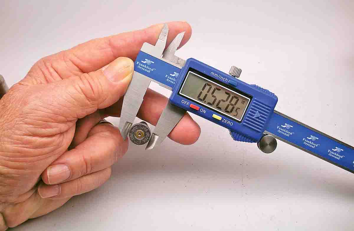
Using a digital blade caliper with a liquid quartz (LQ) readout that reads to four places, that last digit is rounded off to the nearest .0005 inch. As such, if the item measures .5308, it will round off to the nearest whole number, .5310. If the item measures .5304, the readout will round off to .5305. As a result, it is best to validate LQ calipers with a dial caliber, where the needle may measure just over the .530 position, thus validating the .5305 reading on the LQ readout, and shows expansion is roughly .0001 inch less than the maximum allowable of .5305 inch from the original, unfired reading.
Working with rimmed cases intended for use in lever actions, for example, or revolver cartridges, Ken Waters suggested measuring web expansion on factory loads, which shows on a fired case about .3 to .4 inch ahead of the extractor groove as a standard for handloads. Most of the older Winchester lever-action cartridges use a tapered case that tends to back up against the breech face when fired and may show somewhat flattened primers. As such, web expansion offers a good backup for estimating relative pressure signs in relation to factory loads.
Some time back, a mechanical engineer wrote to challenge the accuracy of micrometer measurements taken under anything other than controlled conditions. He was correct, of course, but field work while working for civil engineers surveying and designing roads for the U.S. Forest Service and studying similar subjects in college suggested to me at least that there was a bit of a difference between exacting lab work and the real world out in the field where environmental conditions are what they are.
Even then, if there was an error, it was in addition, subtraction or misreading the instruments, which in the 1960s were archaic when compared to laser-guided instruments in use today. Hitting a four-inch oak stake at the end of a 10-mile survey over rugged mountain terrain, or shooting a line 7,000 feet down an asphalt runway and hitting a nail head at either end in humid heat, freezing rain and blazing hot sun was every bit as accurate as reading a micrometer to four places.
I was also reminded occasionally when reviewing early survey notes on file at the county courthouse, even a chain and staff compass survey, primitive by any standard, was better than knowing nothing. This is not to ignore early surveys that misplaced the Oregon/California border by roughly a quarter mile, or the beer run that ran the Arizona/Mexico border straight from Nogales to the only bar on the Colorado River near present-day San Luis. Precision, it would appear, is largely determined by the motivation of the equipment operator.